What's new
What's new

Need Help with the design of chain drive system

adammil1

Titanium
Joined
Mar 12, 2001
Location
New Haven, CT
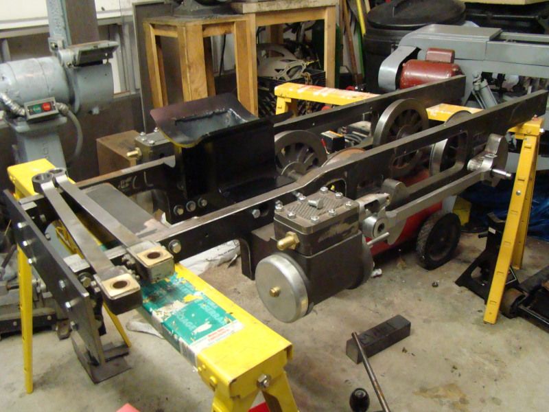
I was wondering if anyone had any ideas. This is the system I have in autodesk inventor;


I need to drive 3, 3" dia rollers 3.5" on center, with one DC gear motor.
Shot of Drive System1.JPGShot of Drive System2.JPG
The challenge I am having is the torque/speed torque per roller is about 300in-lbs (each), and the speed is about 20rpm which is killing me on the chain life calculators, and forcing me to go with #50chain. Making matters worse I need to be able to go in both directions, so I don't even think my current tensioning scheme used in the image above will work.

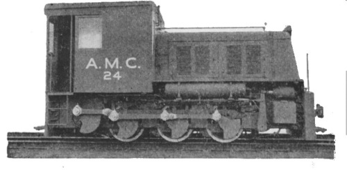
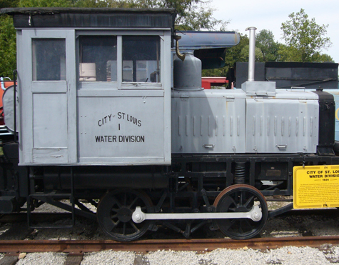
Anyone have any good ideas here, or should I be looking into other options than using a chain such as either gears, or maybe even going with siderods like on a steam locomotive?

Has anyone ever used Snapidle tensionersh ttp://www.snapidle.com/products/chain-tensioners.html? I don't know why they are so expensive (I think they run like $60each at McMaster) If I go double chain width over all 3 rollers forming one big loop, and then use something like these;
belt-6.gif
belt-7.gif

I may be able to get away with it, but has anyone ever used Snapidle products? How well do they hold up with time? On the short spans between the 3 rollers do I really need a tensioner or can I get away without one if I break these into 2 separate loops? If anyone has ever used Inventor's design accelerator for chain, any ideas on getting it to recognize this type of tensioner?

Any other ideas here or am I more or less on the right track?

Thanks

Adam
 
I suggest a motor (with inline reducer) for each roller, direct drive.

I doubt it will be much more expensive, perhaps cheaper.

How much HP are you transmitting? If you can't get the HP you need within 3.5 inches diameter, perhaps one on each end.

No exposed drive, less part numbers to inventory, drive alignments should be easier.

I wouldn't be surprised if self-contained roller/motors were available, with the motor installed in the roller.

Integrated Cylinder Roller for Conveyor Tables
http://www.wittenstein-us.com/Preci...rboxes/alpha-LP-alpha-LPB/videos/LPB070.phtml
 
The horsepower is quite limited, only .2-.3HP it is just the really low speed, (20rpm) that pushes the torque so high. As for individual motors, that just sounds really expensive. I need 18 rollers in the entire assembly! Why the snap idle things are so expensive, I think the one I need for the double #50chain is $100, it just sounds really steep. I suppose when you look at other costs like the 6 gear motors the whole thing isn't going to be cheap overall, but still, it seems like there has to be a better way. I am almost wondering though it will create some higher tolerance demands to get it right if either side rods, or perhaps a gear system could at the end of the day be the way to go. I haven't done any beam calculations as far as what the load that goes through the side rod would be but I do wonder now if it is worth evaluating. I still wonder if there is a better way to do this with chain. Does anyone know of a competing product to the snapidles?

MUD, I would have to look into polychain, HTD or cogged belts but I would think if I am up against the limits of what chain can do I would have a hard time thinking a belt would work.
 
The cogged belt folks have plenty of testimonials where a beefy but troublesome chain drive was replaced with cogged belts, and it results in much much less trouble.

If you outboarded an additional shaft support, you could have a cogged belt seriously wide.

Actually, you could have a cogged belt as the conveyor belt, if you desired. Pulleys engaging the interior of the belt, the belt engaging the material.

Or are you driving directly from rollers to material?

Gates Corporation

Gates Mectrol can produce urethane timing belts in widths up to 450 mm. This belt is specifically designed for synchronous conveying applications.
Wide urethane timing and conveyor belts | Gates Mectrol

Cogged Belts.JPG
 
Well they are flat rollers but must they be timed? Assuming the chain or connecting link proposal and your concern for strength and wear...... the cogged tooth belt might be the easiest, cleanest, neatest way to do this. You have multiple options but say you ran one belt... a single on the drive pulley side and had one idlers between the two end rollers but on opposing sides (like top and bottom viewed from the side) just one idler between each for now and pushing against the back of the belts. This way the middle pulley has sufficient wrap. Now you have one additional idler between the drive and first pulley to get it's proper wrap, so one idler up, one down and one up again. The torque is about 25 ft., lbs and 20 rpm none of which doesn't seem like a lot of force or speed. They have all kinds of idlers, spring loaded, non spring, etc., etc. You may find out you need additional small non adjustable idlers at some point to get the necessary purchase on the pulleys. This looks crazy sometimes but it works and can be done. Look at serpentine belt systems on cars, stock and aftermarket. Look at the belt configuration on commercial mower decks....... that'll give you an education.
 
I don't really know what your making or using it for but yes.... the simple answer is a tiny adjustable sprocket can be used to take up tension, I think also tiny non-tooth idlers are available.
 
Thanks for the replies so far. The rollers are going to be drive wheels running on concrete. One thing I didn't realize is I never thought that belting would be capable of carying more torque than chain/sprocket. But I will have to look into that one further when I get home tonight. One interesting idea I read that I hadn't thought of is can I use a timing belt as almost a tank tread in this application? These will be traveling over concrete, each roller supporting about 5000lbs vertical load on them, and possibly driving over metal chips or whatever else is on the floor. I would think that isn't a friendly environment where a belt would last, but I wonder if they have ones that can do it. If they do that would be almost the ideal situation for me, and then if the center one turns into almost just an idler pully I would think I should be ok. I will have to play with the numbers and see what I can find when I get home later tonight, but has anyone ever seen a belt run directly on the floor as a tank tread?

At any rate I will have to take another look into belting. It will be interesting to see if I box myself into a similar corner as I did with the close center to center spacing with the chain/sprocket system.

Thanks,

Adam
 
Timing belts have come a long way. Gates probably has a 10 mm wide belt that will more than satisfy the requirements for this project. Extrapolating from the fact we have a 30 mm wide timing belt driving a 30 hp spindle on a CNC machine.
 
I did a quick search (I am at lunch right now so more time later tonight) none the less most of the tread type designs seem to have splines on the other side. For what I am doing with the heavy vertical load, I think I more would want to run a simple timing flat belt along a smooth floor. Yet the key issue is what happens if it runs over sand, dirt, metal chips etc... will they all the crap lodge in the belt and chew the thing up? Anyone ever seen a timing belt used this way? My testing budget is not huge and it would be real unfortunate if after building the whole thing they just didn't work.

I was thinking that solid steel rollers with urethane coating would be the way to go like ono rigging skates as at least I know that works. (which this is similar to, but not close enough to use an actual skate). At any rate if anyone has ever seen timing belts used as power treads I would love to know. If there is a good chain type modular tread system I would like to hear of that too. Most systems I saw in my 5mins of search all seemed to be complete treads where if it was the wrong size you were screwed.

As for the table top conveyr track, I googled that and found some sites. Anyone know of a good supplier for it. I don't have any real time to look into this further till later tonight but if anyone knows of a site with details I would be real interested.
 
as to timing belts.
Goodyear Engineered Products has their Eagle line of double-V timing belt. (Not sure if these are available with both sides toothed)
These belts handle very large loads as compared to the size. An added benifit of the design is that the pulleys don't need flanges as the belts are self-aligning.

Eagle NRG
 
You know what makes this difficult to give a sensible answer to...... is that each additional post from the OT provides more information. The rollers are actually running on the ground, over uneven surfaces with metal chips, supporting 5000 lbs vertical load, etc., etc. If this is something you're trying to invent and patent and sell
it makes sense to play it close to the vest. If it's just for your own personal use...... you should give all available info because then you'll get flooded with different ideas, many might never have occurred to you. You can pick and choose and still build it yourself and it will be your own personal project and success story assuming
the original premiss makes sense, but even that very well might be answered here. Anyway..... stuff like that is fun to play with and fabricate, good luck with it.
 
et the key issue is what happens if it runs over sand, dirt, metal chips etc... will they all the crap lodge in the belt and chew the thing up?

Ask a Harley mechanic....when a pebble gets between the final drive belt (on some Harleys) and the pulley, it seems to fail gracefully, not catastrophically. The pebble may puncture the belt, raise the belt off the pulley etc.

But Harley hasn't stopped using them.

http://www.v-twinforum.com/forums/h...-hours-does-take-replace-fxrs-drive-belt.html
 
The simplest and least expensive way is to use 3 drive gears and 2 idlers. Straight spur gears are available from Boston gear and they are inexpensive. I would use steel drive gears and nylon idler gears. Mounting the idlers with an adjustable flange (slotted holes) would allow fine backlash adjustment. The solution is simple, compact, inexpensive, silent, easy to build and self lubricating. You can order the gears with or without a boss and with or without keyways.
 
You know what makes this difficult to give a sensible answer to...... is that each additional post from the OT provides more information. The rollers are actually running on the ground, over uneven surfaces with metal chips, supporting 5000 lbs vertical load, etc., etc. If this is something you're trying to invent and patent and sell
it makes sense to play it close to the vest. If it's just for your own personal use...... you should give all available info because then you'll get flooded with different ideas, many might never have occurred to you. You can pick and choose and still build it yourself and it will be your own personal project and success story assuming
the original premiss makes sense, but even that very well might be answered here. Anyway..... stuff like that is fun to play with and fabricate, good luck with it.

I am not quite sure what direction to go right now. It sure is fun to play with and an interesting challenge but this may actually be something I want to try to put into production if I can get it to work, and try to sell so I would prefer not to give everything away right now. I think I have mentioned all the major requirements that it has. I expect that this device will perform on level concrete floors similar to what you would place a normal rigger's jack on, there could be crud on the floor just like any other would be. As such original plans were to build this thing very similar to how one would construct a rigger's jack where heavy duty urethane coated wheels support the load, only mine are to be powered.

..and no one has ever moved a load before you sat down at a CAD terminal?

Don't just assume an approach and seek a material.

Research what has already been done. Search on how the problem has previously been solved. 'Coz it IS solved, every day of the week somewhere ... or many 'somewheres', and was being solved long before the first pyramid was built in Egypt.

One example among many:

Hilman Rollers - Leading manufacturer of rollers, load skates, and material handling equipment

There are others. And they know how to keep their chains and belts from stretching, breaking, or sliding off under turning or lateral thrust, and have experience with uneven floors and debris.

It's wot they do...

Which design of Hillman's were you referencing, the only thing that comes close I see is their tracksporter, but other than some exterior photos no clue how how their treads are put together nor do I want to pay $100K to buy one and take it apart either!

Actually the more I have been thinking of it and looking at the prices of belts, and the likes and realizing I am getting into some real money here, the more and more I can't help but think that this indeed could be the better more time proven system I should be going for;
mcgrawA158_4.jpg

In my case since I plan on making the whole thing from a weldament made from flame cut burnouts the holes for the roller bearings to sit in to support the axles will yeild as scrap the perfect pieces to create an eccentric crank with as scrap I am thinking more and more that this may be the way to go? Other than the fact that I will have to keep the tolerances real tight is it possible our forefathers of engineering 100yrs ago had the best solution for very low speed high torque loads or should I still be thinking in terms of belts and or chains here?
 
The back of rubber belts like HTD belts is pretty tough, feels about like conveyor belting. It can be cut with a utility knife, sharp chips and etc will embed in it like in pallet jack wheels, but stones and etc shouldn't cut it unless you have enough pressure to push it completely through. Even then, they will run for a long time under power as long as the cut is not on the edge.

Other belts like Polychain and the Eagle belts the back is hard plastic and has a sharp edged pattern with grooves across the belt, they would be tougher but slippery against the floor. They are also a lot stiffer, the eagle belt requires a jack device to stretch it out for installation. Tooth shapes vary, the HTD shape has several manufacturers and compatible styles which is an advantage when buying and designing.

I'd choose 8mm HTD or powergrip GT belts for your device. A 28 tooth pulley would be about 3" OD over the belt. Cogged belts don't wear or stretch so you can mount the shafts on fixed centers with no adjustment and just install the belts and tension will be correct with no tensioners or idlers. I can help you calculate the C-C distance if you need that. Belts are available in 20 30 50 and 85 mm widths from stock in 60 70 75 80 90 100 110 120 130 140 150 and 160 tooth lengths. You can get them wider or narrower on special order, non-stock lengths are available too when you get the right suppliers. I can help you there too, and probably cheaper than your local distributor. For example an 8mm belt 50mm with 120 teeth long is about $60 one at a time.

I can cut pulleys up to 5" wide on gear shapers, you can also get any width hobbed. There are suppliers that stock pre cut pulley stock in steel and aluminum in stock lengths like 12" long, a piece like that might be ideal for your axles. here's an example - Timing Pulley Bar Stock | B&B Manufacturing OEM stock pulleys are priced outrageously, you can make exactly what you need instead of adapting the cast iron Gates pulleys for 1/4 the price. There's no rocket science about making them, and the patents have expired so there's no longer any royalties to pay.

On another tack, have you considered regular V belts for the tracks?

To drive the axles, 8mm would work there too. 22 tooth is about as small as you want to go, that would give you a pulley about 2.3" diameter.
 
Bill, the side loads are a point I hadn't really considered with this having to steer a bit side to side I think that is the real killer to using flat belts of any sort. If I can't trust them to stay on when this thing turns I don't think it will work, so I am going to stick with the urethane coated wheels as I know they work and are used by all the rigging equipment makers. Thus I think I am back to the conclusion of using rollers as the best way to go.

As far as the eccentric cranks go I am quite familiar with them. Here they are on the current live steam locomotive I am building so no need to go too far away to look at one;
DSC01182.jpg

The key issue when building one of these that one must be sure is the center to center distance of both the axles, the shafts, and the crank pins needs to be perfectly equal, as well as the cranks need to be 90deg perfect to the opposing side or you have big issues.

If you go this route applying 440inlbs of torque over the system, seems to yield a very high factor of safety when using a 1" thick bar by .5" wide with .5" dia pins just to get close. So I think it is looking like it is by far the most economical route right now but if I have any deformation under load I am screwed!

Actually thinking of it some more all almost all of the old diesel electric switching locomotives that were single traction motor per truck use side rods, so I must not be the first to realize its efficiency in high torque, low speed single motor driving multiple wheels problem before. Here's a few examples;
2009_05.jpg
RGE1941_Roster_Large.jpg


So now I guess I have to decide in general the route to go. I am quite worried about overall deflections that could take place by going the side rod route, so belts may be the way.

Mud, say I want to put these wheels 3.25" on center with one another (though I still can move it if there is a stock belt size I am close to), at this point going with the tread system is out, so any timing belt that can stretch over the outside and not need a tensioner of any sort would be ideal. Can I slip one belt over all 3 axles or do I need to separate it so one drives the front two one the rear two and a 3rd goes to the motor? By the way, I like your idea of buying the stock lengths of timing belt shafting and cutting the pullies as needed, what would you recommend in terms of belt size and series to use here now that it won't be used as a tread, but rather a drive belt? Once again size it to be about .2HP and 20rpm. Keeping overall width to a minimum would be a big help but the pullies have to be less than 3" OD and even less would be better.

Thanks,

Adam


Back
Top