How to install the app on iOS
Follow along with the video below to see how to install our site as a web app on your home screen.
Note: This feature may not be available in some browsers.
Largest Manufacturing Technology Community on the Web
Stay Connected:
You are using an out of date browser. It may not display this or other websites correctly.
You should upgrade or use an alternative browser.
You should upgrade or use an alternative browser.
g76 for dummies
- Thread starter eli
- Start date
- Replies 34
- Views 55,098
machine1medic
Titanium
- Joined
- Jul 1, 2006
- Location
- Clover Hill district, WI
use explained
I can't swear to which is which but .....
where as G86 just stops at the bottom of the bore and drags the tip
back to the top along the bored wall.
Your G76 needs to know at what point you need the boring tip to be
oriented to, so that it knows the tip is being moved away from the wall
and not into the wall.
It also wants to know on some machines how far (incrementally)
to retract away from the wall.
Since some tooling needs to be loaded with the offset drive lug
at the spindle orient position, and some machines the tooling
can go in either way; the G76 wants to know if your mounted
boring tooling can just retract at the spindle orient position,
or does it need some other rotational position for the tip to be retracted away.
Two of the variables define the location in the same way that I and J
give arc-center location......one variable might just be an absolute angle.
I would use the variables with the tool above the work to prove out
which is which on your machine.
All this is subject to correction......I'm rusty on boring with G76.
m1m
PixMan
Diamond
- Joined
- Jan 30, 2007
- Location
- Central MA USA
On most machines (lathes, typically) the G76 is a compound infeed angle threading cycle, not a boring cycle.
In the first G76 line:
"P" uses 6 digits. First pair is number of passes @ final diameter. Second pair of digits are number of turns (or "leads") for pull-out as the tool nears the end of the stroke. Third pair is included angle of thread.
"Q" is the incremental amount of the "clamp value", which means this is the smallest depth of cut (per side) the cycle will use until it reaches the amount left for final pass.
"R" is the incremental amount (per side) left for the final pass.
In the 2nd G76 line:
"X" is the root diameter of the thread if it's an O.D. thread, or the max diameter if it's an internal thread.
"Z" is the end point of the thread stroke.
"P" is theoretically the incremental height (per side) of the thread. You can alter this a little to assure extra clearance on the retraction, but it's not necessary.
"Q" is the incremental depth (per side) of the 1st pass. Altering this one can have one of the biggest impacts on the total number of passes. If using full profile threading inserts, don't mess around. Make this a big number and git 'er done.
"R" is optional, and represents the incremental amount of taper. Use this for making pipe threads, for instance.
"F" is the thread pitch or lead, whatever you choose to call it.
That's my explanation for G76, there will be other opinions.
machine1medic
Titanium
- Joined
- Jul 1, 2006
- Location
- Clover Hill district, WI
On most machines (lathes, typically) the G76 is a compound infeed angle threading cycle, not a boring cycle.......................
............................That's my explanation for G76, there will be other opinions.
Well that pretty-much looks like what he wants.
I wondered what the two different lines were for.
CNC turning is Greek to me.

")
Thanks for clearing it up.
m1m
Heinz R. Putz
Stainless
- Joined
- Mar 16, 2006
- Location
- Columbus, Ohio
Here is a pretty much fully explained Example from my website:
www.doccnc.com
G76 in 2 line format for OT and later controls.
2" diameter, 20 Threads per Inch, Mild Steel.
O2006*
N1 G50 S1500*
N2 T0101*
N3 G97 S700 M3*(Speed for threading, always in RPM)
N4 G0 X2.2 Z.2 M8*(Rapid to above part, .2" from face)
N5 G76 P021060 Q20 R5*(The first 2 digits in P represent the amount of finish passes, the next 2 are the pullout distance at the end of the threading motion, expressed in tenths of revolutions, the 60 is the angle of the tool)
N6 G76 X1.94 Z-1.0 P300(total thread depth) Q150(depth of first cut) F.05*
R if needed is the amount of taper over total distance in thread motion.
The P value is figured by taking the F-value times the constant of .6, once figured you also have the X value.
N7 G0 X6.0 Z6.0 M9*
N8 M30*
Good luck in learning more about CNC.
Look over the DVDs if you need detailed help.
Heinz.
allen3944
Aluminum
- Joined
- Feb 16, 2009
- Location
- south carolina
where did you get that constant of .6 for the p value???
Heinz R. Putz
Stainless
- Joined
- Mar 16, 2006
- Location
- Columbus, Ohio
I got it from Fanuc, way back when I used to teach the 6T class for them in Chicago.
The exact value is a little more, its .62 times the feed to the best of my recollection.
After a lot of discussion with my Japanese Fanuc guys, we decided to use .6 times the feedrate for our constant to figure the depth of thread.
The reason we use a smaller number is that we will get a tight thread, we can always recut with an offset change if the thread is too tight, but if the thread is too deep, we have to throw the part away and that's a no,no.
Remember, this is only good for a 60 degree thread.
There are a lot of other examples on the website, both for turning and milling, if any of you need to learn more.
Heinz.
www.doccnc.com
Our old Mori Seiki only reads the single line G76 cycle, and one thing the single line is great for is that the Q designates what degree of rotation to start the thread at, VERY useful for doing multiple start threads where you must start and stop in a confined area. I've started and stopped 4 lead threads in a 1/4" wide relief before using this. And on machines that read the double line they should have a "soft switch" that converts them to read the single line. The code looks something like this for an internal 4 lead 3" thread.
X is Major dia. of thread
Z is length
I is for taper amount if any, some machines use R here I think.
K is for single depth
D is depth per pass (our machines require this to have no decimal point)
A is included angle
F is feed
Q is start point in degrees of rotation (our machines require 3 zeros after the actual #)
G0 X2.85 Z.25
G76X3.01Z-2.96I0K.06D005A60F.4Q0000
G76X3.01Z-2.96I0K.06D005A60F.4Q90000
G76X3.01Z-2.96I0K.06D005A60F.4Q180000
G76X3.01Z-2.96I0K.06D005A60F.4Q270000
G0 X2.85 Z.25
Ox
Diamond
- Joined
- Aug 27, 2002
- Location
- Northwest Ohio
The P and Q's are always posted in non-decimal format and generally posted in 4 position values. (.1234" = 1234) However Heinz did not show this very well as he ommitted the preceeding 0's in his format.
Also note that some machines are set to a 5 position format as well. .015" = 01500
-------------------
Think Snow Eh!
Ox
Also note that some machines are set to a 5 position format as well. .015" = 01500
-------------------
Think Snow Eh!
Ox
Last edited:
Heinz R. Putz
Stainless
- Joined
- Mar 16, 2006
- Location
- Columbus, Ohio
Hello Cuda:
That is a really unusual way to do multiple threads, in fact, I have never seen it before.
What control do you have on the Mori?
The normal way to do a 2 lead multiple lead thread is to move the startpoint back in Z by 1 lead and then repeat the G76.
Lets say you have a 10 pitch double lead thread on a 2" diameter, it would look like this:
G0 X2.1 Z.1*
G76 P021060 Q0020 R0005*
G76-----F.2
G0 Z.2*
G76---
G76---
etc.
One thing you really have to watch when programming multiple lead threads is that you don't exceed the max feedrate available.
On Fanuc, the max is usually 300 IPM, so your RPM times the feed per rev better not exceed that.
By the way, the Q and R with the extra digits are meant to please Ox, he is quite particular about details, and rightly so.
Heinz.
www.doccnc.com
Ox
Diamond
- Joined
- Aug 27, 2002
- Location
- Northwest Ohio
he is quite particular about details
... well if your trying to learn someone something new .....

--------------
Think Snow Eh!
Ox
Hello Cuda:
That is a really unusual way to do multiple threads, in fact, I have never seen it before.
What control do you have on the Mori?
The normal way to do a 2 lead multiple lead thread is to move the startpoint back in Z by 1 lead and then repeat the G76.
Heinz.
www.doccnc.com
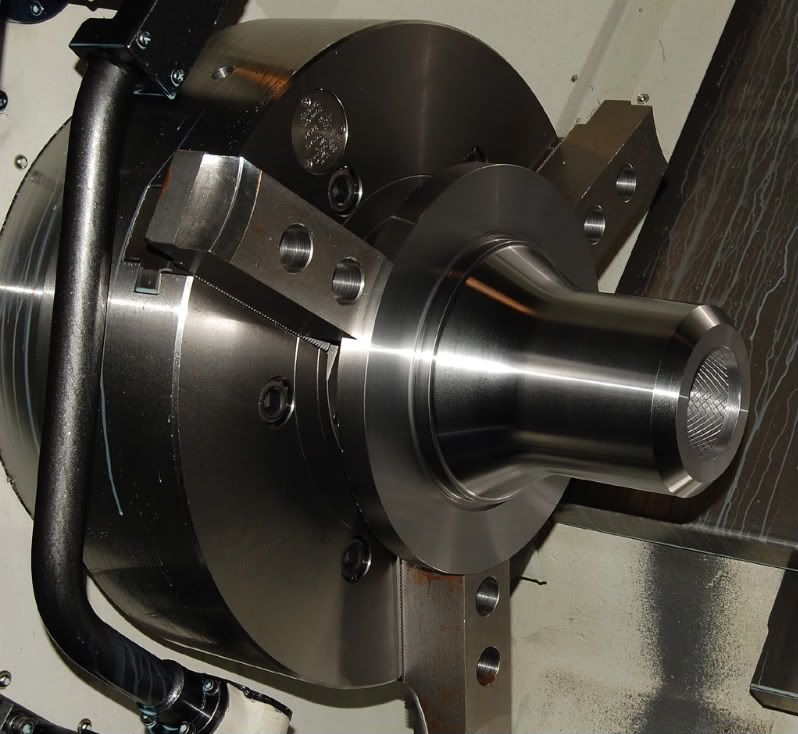
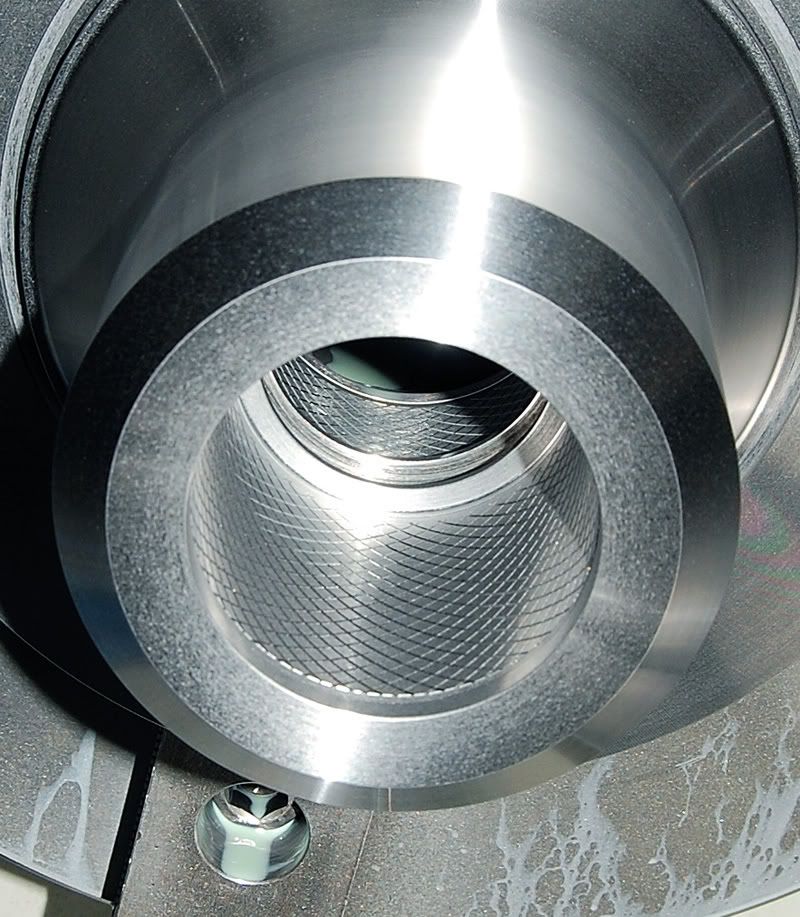
Try it sometime, it works great, but only works with the single line G76, I had to do an 8 lead square grease groove one time that had to start and stop in a 1/4" wide groove, that would be impossible to do by shifting the Z start point as there isn't enough room, so we called the guy that set up the machine for us and he told us how to do it. And I have done this on our Mori SL 25 with Fanuc 15T and our Daewoo Puma 400 with 21T. Here is a knurl type pattern I cut into a bunch of parts awhile back using the same code, it was just for holding glue for a pressed in Teflon bushing, you can see the pattern starts and stops in a narrow groove .
PixMan
Diamond
- Joined
- Jan 30, 2007
- Location
- Central MA USA
That's a nice-looking piece, well done!
I see no reason why shifting the start point of Z to use the two-line G76 code wouldn't work for a task like that. After all, the end point of Z doesn't change and that's the important part.
Oops, I just realized you said you were starting AND stopping between two grooves, so you're right that the two-line G76 and a Z shift wouldn't work.
Solar71
Titanium
- Joined
- Mar 24, 2005
- Location
- Hermosa Beach California
WOW that part looks just like a part that we make here in our shop.
Except that the Larger diameter behind the large nose sticking out forward, gets a Bolt Circle drilled into it with large counter bores.
But its nice looking either way.
Except that the Larger diameter behind the large nose sticking out forward, gets a Bolt Circle drilled into it with large counter bores.
But its nice looking either way.
WOW that part looks just like a part that we make here in our shop.
Except that the Larger diameter behind the large nose sticking out forward, gets a Bolt Circle drilled into it with large counter bores.
But its nice looking either way.
Yeah, that part got a bolt pattern drilled into the large flange that I'm chucking on, but that's done last in a Fadal.
gorrilla
Stainless
- Joined
- May 2, 2007
Pix man, I believe you are right. Your description fits the way I've written G76 for years. You even explained the first item in the first G76 line even better than I understood it.
RedJeepGuy
Plastic
- Joined
- Sep 27, 2013
- Location
- St. Louis
I'm glad I found this because I'm a true dummy here.
We are running some 3/8-16 threads in stainless steel that are eating inserts and giving a poor finish. I'm trying to figure out exactly what effect all the parameters will have on the process.
We're using an 16ERMAG60 TT9030 insert and it is programmed as:
N4(3/8-16 3A THREADS)
G97M13S2000
M98P1
T0404
Z4.825
X.475
G76P040030Q0020R.0010
G76X.299Z.94P0383Q0020F.0625R0.
G0X4.0
M98P1
M01
If I understand it correctly the 04 in the first P line is going to make it do 4 finish passes at the final depth.
(Question 1) Does this mean that it will turn the threads down and leave .010 per side, and then in 4 finish passes take that .010" material off? Or does that mean after it gets down to size it will run 4 additional passes all at the same final size?
The next 00 in that P word is going to cause it to not do any chamfer on the end of the thread where a 10 would make it do a 1/16" chamfer. (1.0 x .0625 pitch) And a 20 would make it do a 1/8" chamfer.
The next one is causing some debate in our shop. I am reading the operator's manual, the programmers manual and the posts above to say that number should be 60 for the insert we are using 16ERMAG60. The old time tribal knowledge in the shop is saying it should be half of the thread angle which is why they have it at 30. ("That's the way it's always been") But the programmer's manual says the 6 possible values for this term are 00, 29, 30, 55, 60, 80 degrees. Well, if it were double, a 160 degree insert would seem silly.
(Question 2) What should it be for this insert?
(Question 3) How exactly will the tool path be different if that number is 30 or 60 (or 0 or 80)?
Still in the first line, the Q word will make it take a min .002" per pass and the R term will make it leave .010" per side for a finish allowance.
On the 2nd g76 line we have the minor thread diameter of .299 for 3/8-16 threads in the X word. The Z is the length of the threads.
The 2nd line P word is the Single Depth of Thread which the Hardinge programmers manual says is calculated as .61343/TPI for a straight thread which in this case is .61343/16=.0383 giving the term P0383
The 2nd line Q word is the depth of the first pass and we have it at Q0020 which means that we are only taking .002" on the first pass. (Question 4) Does this mean that it will take only .002" for each pass? The programmers manual says this should be calculated as the (single depth of thread) / (the square root of the number of passes). If so, I get something like 366 passes would produce the .0020 value? But when it runs it is only doing 23 passes. Using that formula, for 23 passes it should be Q0080 and for 12 passes it should be Q0110. (Question 5) How does this number affect the number of passes and the depth of cut of each pass?
F.0625 is the lead and R0. means no taper on the threads.
Here are links to the pages in the manuals I found that pertain to the g76 on the fanuc controllers.
Hardinge Programmer's Manual g76 pages
http://www.filedropper.com/g76programmersmanual
Fanuc Operator's Manual g76 pages
http://www.filedropper.com/fanucoi-tcg76pages
So, there are 5 questions in bold above and any help with those would be great.
Thanks in advance.
Ox
Diamond
- Joined
- Aug 27, 2002
- Location
- Northwest Ohio
Real quick (I gotta leave)
G76 P010160
----------------------
Think Snow Eh!
Ox
G76 P010160
----------------------
Think Snow Eh!
Ox
This is just another explanation of the cycle. Maybe it'll help...
A copy n paste from my manual.
G76 – THREADING CYCLE – TWO LINE FORMAT*(FS 0,16,18,21T,31i,32i, -FORMAT)
(Applicable with Fanuc Controls, T series, systems 0,16,18,21,31i,32i.
Also: Mitsubishi 500L, 50, 64)
FIRST COMMAND LINE:
G76 P021060 Q05 R10 (See detailed explanation, below)
P 02 10 60 Specify “P”, followed by a six digit number. Translation is shown, here:
02 =Number of finish passes at the bottom of the thread (02 means 2 Passes) (Sets PAR 5142– see note 1)
10 =Chamfer-width or pullout-width at the “Z” end position of the thread. Chamfer size is expressed in1/10th fractions of the lead.
10: means the chamfer-width equals one lead.
05: means the chamfer width equals ½ of lead.
00: means no chamfer.*See note 3, below.(Sets PAR 5130)
60 =The included angle between the thread flanks. ½ of the angle as
Specified is applied for the in-feed angle. Normally, 60°*is used for standard threads.
Other angles, such as: 80°, 60°, 55°, 30°, 29°or 0°*can be specified (Sets PAR 5143)
Q05 =Minimum cutting depth (depth of cut becomes progressively smaller, after each pass.
Remainder, smaller than “Q” is discarded (Sets PAR 5140).
R10 =Material allowance for finishing passes at bottom of thread (Sets PAR 5141)
SECOND COMMAND LINE:
G76 X__ Z__ P100 Q200 R300 F0.038461 (See detailed explanation, below)
X =Diameter of the thread. For an external Thread – specify the minor diameter.
For an internal Thread - specify the major diameter.
In case of taper threads, specify the diameter at the opposite end from the start point.
Z =End position of the thread.
P =Height of the thread. Calculation: Major diameter minus minor diameter, divided by 2
(Radius value, without decimal point) See note 2, below.
Q =Depth of the first cut. If “P” and “Q” are the same, then the
Thread is `cut in a single pass. (Radius value without decimal point) See note 2, below
R =Taper. (Radial height difference of taper slope, per side)
Specify a negative value for OD taper thread.
Specify a positive value for ID taper thread.
F = Lead: distance between two threads. (1 divided by the pitch), six digits allowed after the decimal point.
NOTES:
1.) Upon execution of the G76-cycle all data contained on the first
G76-command line is automatically stored in the parameter tables.
2.) Values for “P” and “Q” to be specified without decimal point for all Fanuc Controls.
For example:
0.0001” =1
0.001”** =10
0.01”**** =100
0.1”****** =1000
1.0”****** =10000
3.) Specifying a chamfer (pullout distance) reduces possible damage to the last thread lead near the Z-end position.
*
Try changing P040030 to P040055
See thread at the bottom...
I posted this (at the top) in another thread. Its one of the easiest explanations of the two line G76 cycle for me to understand. Hope it helps...
Brent
http://www.practicalmachinist.com/vb/cnc-machining/thread-cuttting-issues-307094/
Similar threads
- Replies
- 37
- Views
- 3K