What's new
What's new

The Portsmouth Blockmaking Machinery

Asquith

Diamond
Joined
Mar 3, 2005
Location
Somerset, UK
I showed a few photos of machines for producing ship's blocks in this thread:-

http://www.practicalmachinist.com/vb/antique-machinery-and-history/bramah-maudslay-319723/

The machines were installed at Portsmouth Dockyard, starting in 1803, and had a very long working life. Marc Brunel was responsible for the design of the machinery. Henry Maudslay was contracted to make them, and he would inevitably have been involved in the detail design.

The blocks were for the rigging of the Royal Navy's ships, and at the time over 100,000 new blocks were needed every year. In addition to quantity, quality was of prime importance, to avoid the risk of jamming during close-quarter manoeuvres in battle.

The machinery was designed for fast, interchangeable production.

Having offered to post pictures of the machines, I realise that having lots of pictures is one thing, but describing their use is another matter, especially as I haven't studied them in depth. I have found good but lengthy descriptions of the production of the blocks, but can hardly transcribe them to this thread. We'll just have to see how we go.

Wkipedia has a good write-up, but lacks photos of the machines.

Portsmouth Block Mills - Wikipedia, the free encyclopedia

Here's a picture of a block:-

http://cache4.asset-cache.net/gc/90742458-ships-pulley-block-made-on-portsmouth-block-gettyimages.jpg?v=1&c=IWSAsset&k=2&d=X7WJLa88Cweo9HktRLaNXoh%2BYEO3f24soRziKuBLTDFAK6jzy1tyoJWtzdr8ye3DJc6ac4la1HBGEdDAzXUFD9siN2veX33735VOmDgjNLM%3D

Various sizes were made, having either one or two pulleys (sheaves) or no sheaves at all ('dead eyes').

A single sheave block had eight components:-

Elm block, with a hole for the sheave's pin, a slot for the sheave and rope, and grooves on the side faces for the fixing ropes.

A sheave made of lignum vitae. This was faced on the side, grooved on the rim, and bored for a bush - a bell metal casting known as the coak. The casting had a three hole flange on one side, and a loose flange on the other. On assembly, three holes were drilled through for pins, and these were riveted over by a machine to secure the coak.

A burnished pin with a square end was the pivot for the sheave.

The London Science Museum published a 42 page booklet in 1965 called The Portsmouth Blockmaking Machinery, by K R Gilbert. He listed 22 types of machine at the Portsmouth Block Mills. In some cases there were several examples, making 45 machines in total. 8 went to the Science Museum and 6 remained at Portsmouth. 8 of Maudslay's models went to the National Maritime Museum. Unfortunately there is much overlap in the surviving types, so only 10 types are represented by actual surviving machines or models. Looking at photos, it is clear that where machines were duplicated, there were design changes. Presumably all the ones in the Science Museum are the original version.

Some or many photos will follow.
 
Those boring machines

B1

B2

We'll start with the elm blocks.

Various sawing machines, including a pendulum saw, were used to cut truly rectangular blocks.

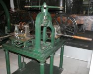
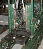
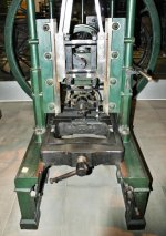
The blocks went to one of the boring machines (there were three), where they were clamped in a fixture. Two headstocks carrying drills were advanced upon the block, one making the hole through the face for the sheave's pivot. The other came in at right angles to the first, and made a larger hole nearer the top of the block, which was the starting point for subsequent cutting of a mortice for the sheave.

The screw press which holds the block in place also impresses the ends of the block with register marks which are used to locate the block in subsequent operations.

I asked myself how they lined up the blocks before clamping them down, but found that I was the wrong person to ask. My photos do show a couple of brackets with small protruding buttons, so perhaps they were stops for the blocks. No, I didn’t take enough photos.

JD Block boring5.jpgB3 JD Block boring1.jpgB4 JD Block boring2.jpgB5 JD Block boring3.jpgB6

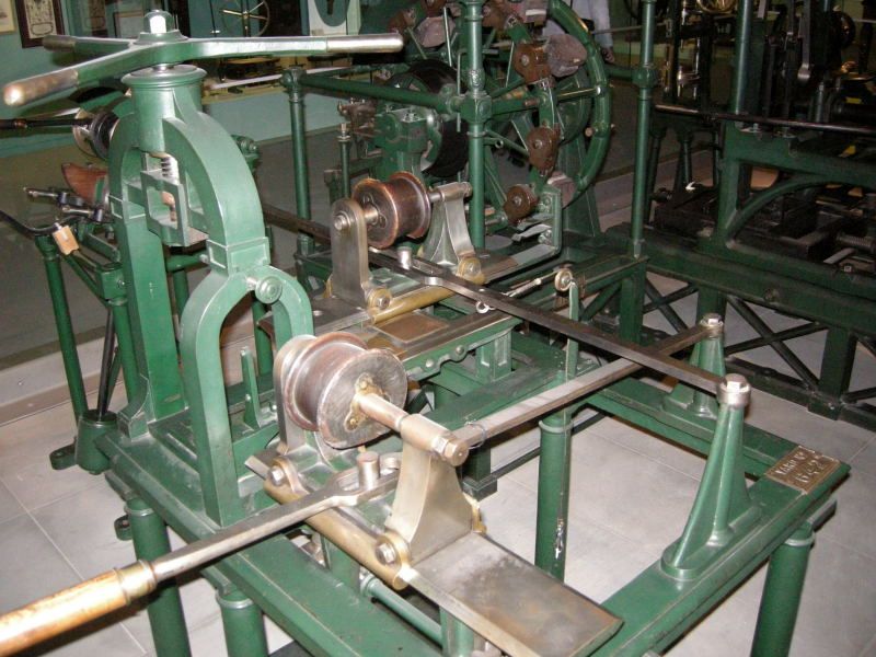
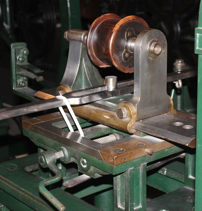
I see from my photos that the boring head for drilling the pivot could be elevated on V guides by means of a rack and pinion. The handle for raising it has an indexing wheel. See photo B3 (enlarged from B4). The other boring head can't be elevated, but it can be traversed by a cross slide guided by dovetails. This was used when boring an extra hole in the case of double-sheave blocks. I see from photo B2 that to the right of the leadscrew there’s the recessed head of another screw, and below that is a flat handle. Possibly some form of detent to establish the positions of the two holes?

The spindles are threaded internally to accommodate the drill. I see no provision for lubricating the spindle bearings.

Note that the drive pulleys, like the sheaves, have ‘coaks’ secured by 3 pins, and that the flanges are recessed to finish flush with the pulley. We’ll see how they did that in a later post. Possibly much later.

Looking at photos of a boring machine which remained at Portsmouth, I note that there are certain differences, including cast iron instead of wooden pulleys:-

http://www.builderbill-diy-help.com/image-files/brunel-boring-machine.jpg

Presumably this was a later machine than the one at the Science Museum. Other variations can be seen in this drawing:-

http://media.gettyimages.com/photos/book-the-cyclopaedia-universal-dictionary-of-arts-sciences-and-rees-picture-id138602896

It has two-speed pulleys. A bigger difference is in the mounting of the head for boring the holes for the sheave slots. Instead of having a leadscrew-operated cross slide, the headstock is mounted on a rocking support. Also, the clamping screw has a fly press-type handle.
 
M1

M2

I'm only slowly beginning to appreciate the true wonder of these machines. This collection deserves to be a place of homage for all those keen to understand the significance of the Industrial Revolution. The problem is that most people, even those most enthusiastic about old machinery, will find it difficult to view the system in the context of the time – c.1800.

In terms of precision engineering they were clearly preceded and bettered by various scientific instruments, dividing engines, etc; while for examples of shear ingenuity applied with dogged persistence to mass production, 18th C. textile machinery surely takes the prize. However, as a demonstration of ingenuity applied to a group of 22 types of machine tools combined with the rare ability to make the required parts, I think the Portsmouth machinery would be hard to beat. I should qualify that by saying that Matthew Boulton’s coining machinery might well be up there on the podium, but I don’t know enough about it, and it hasn’t survived to be scrutinized.

The successful implementation of the block mill concept depended on the fusion of the minds of two brilliant people. We should also recognise that it also needed the effort of other individuals, known and unknown. The known ones include Sir Samuel Bentham, and a M. de Bacquancourt who brought Brunel and Maudslay together.

If I had to focus on just one area of these machines as an indicator of the great leap forward in engineering, it would be on the mortising machine, specifically in the flywheel area. I'll explain why I think this is so, presently.

JD Mortising03.jpgM3 JD Mortising04.jpgM4JD Mortising08.jpgM5JD Mortising05.jpgM6JD Mortising06.jpgM7

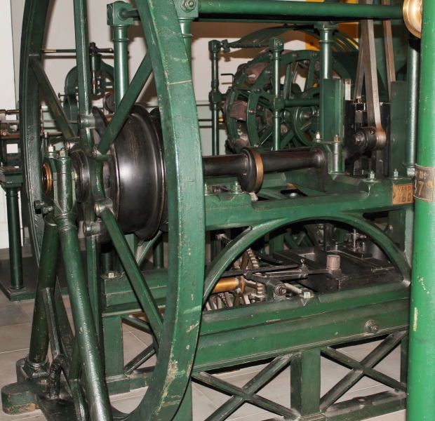
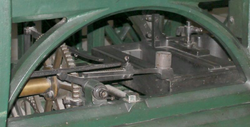
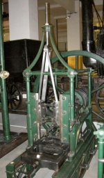
The mortising machine used reciprocating chisels to cut the slots for sheaves, starting at the hole(s) made earlier in the boring machine.

The basics – Flywheel – crankshaft – reciprocation – chisel holders.

Two mortising chisels were fitted, either to slot two blocks or to cut two slots in one block.

The blocks are clamped in the vice-like frame. The fixed jaw of the vice is not actually fixed, as it can be repositioned to accommodate different sizes of block, the frame having large buttressed teeth to support the 'fixed' jaw. The frame is moved horizontally in dovetail ways by a large leadscrew. This is surrounded by a nut driven by a ratchet wheel. See photos M5 & M7.

The ratchet linkage is worked by a cam on the crankshaft. K R Gilbert wrote that the blocks in their frame advance at 1/24" for each stroke of the chisels, and 'At the working speed of 400 strokes per minute the chisels cannot be distinctly seen and the mortises are observed to lengthen without evident cause.'

If we think of the machine as a vertical engine, 400 rpm seems an incredible speed for that era (especially as there are no oil cups – presumably just oil holes).

Was it 400 rpm, though? An account in the 1854 Cyclopaedia of Useful Arts says 110 – 150 strokes per minute, and 'cutting at every stroke a chip as thick as pasteboard with the utmost precision.' 1/24" does sound about right for pasteboard, does it not? But at 400 rpm it would only take about 20 seconds to cut a 6" long slot. Too fast? There are 24 teeth on the ratchet wheel, but surely the screw thread pitch isn't 1 inch? K R Gilbert reproduced a page from M. Brunel’s notebook relating to the mortising machine. He wrote 1¾ Diameter two threads sqr. ½ inch in a turn. So, ½" pitch, giving 1/48" advance per stroke.

When the frame has travelled its allotted extent, a weighted lever which was resting on the moving frame drops off, disengaging the ratchet. This can be seen in photo M2. The original concept can be seen in the ¼ scale model which preceded construction of the plant:-

http://collections.rmg.co.uk/mediaLib/660/media-660000/large.jpg

More good photos of the model here:-

Structural model; Mortising machine - National Maritime Museum

I was initially puzzled by the 'rhunic symbols' on the vice jaw. I eventually realised that they are the locating features corresponding to the impressions made in the ends of the block by the boring machine. Two for the single sheave blocks, and a different type for the double sheave block.

Inboard of the flywheel is the drive drum. Within this there is a cone clutch operated by a long lever. K R Gilbert wrote that that this is believed to be the first instance of the use of a cone clutch. The male part of the clutch, keyed to the crankshaft, has cones at both ends, and moving the lever further in the disengaging direction brings the other cone into contact with another female cone – the brake.

The clutch and the ratchet can be seen in this drawing:-

http://media.gettyimages.com/photos/book-the-cyclopaedia-universal-dictionary-of-arts-sciences-and-rees-picture-id138602897

The flywheel looks to be a fine and bold example of foundrywork. The slender spokes would solidify and contract much quicker than the heavy rim, risking cracking of the spokes or of the hub.

The clutch/brake flywheel unit seems incredibly advanced for c.1800. To me, this epitomises the brilliance of the work. It was ingenious as a concept (Brunel), and dependent on what was then rare machining capability (Maudslay), together the skill of the unknown foundrymen. The turning of the relatively large matching male and female tapers could not have been routine at that time. Fortunately Maudslay had produced lathes with compound slides. He had probably seen the Verbruggen's cannon turning/boring machine during his time at Woolwich Arsenal. This had a form of compound slide. Then, in 1794, when Maudslay was working as Joseph Bramah’s right hand man, the Bramah compound slide rest was patented.
 
Asquith,

Many thanks for your efforts and time spent in researching and compiling the information in this thread. I have read about the Portsmouth block making machinery, but without a clear explanation supported by explicit photos such as you have supplied here, it was difficult to visualise how the individual items worked. Your detailed photos and explanations really do make a difference. I hope the Science Museum will keep a copy of this thread as a "layman's guide" to how this machinery operated. Congratulations on producing a first class historical document.

franco
 
400 strokes per minute could be one up stroke and one down stroke which would give 200 rpm of the flywheel which still seems fast for the diameter of the wheel. I am guessing the diameter of the wheel is about 5' which would be pretty scary at 200 rpm, 100 would seem like a good speed. The finish is amazing considering what a steam engine looked like at the time. I imagine they were extremely expensive machines when new.
 
Asquith, thank you so much for making good on your word, and starting this thread! The sliding "headstock" for boring the blocks is so counterintuitive, what with the modern use of splined shafting/couplings, but the Brunel/Maudslay solution is much more elegant in its simplicity (and no doubt ease of manufacture!). Please continue on down the "block making line", so to speak. How were the pins held fast to the block, one side was square, no doubt to keep it from rotating, but the other side??? Again, thank you for your in-depth descriptions and explanations, your contributions are a treasure for the whole forum. -Andrew
 
Many thanks for posting these pictures, explanations and the links to more information. I would have never in my wildest dreams imagined that something as simple as a block would have been produced this way in the early 1800s. I'm am amazed at the ingenuity of the machines and the process. I guess I thought in the early 1800s men were still banging away with a hammer and chisel. ;)
 
Thank you, this is fantastic. Your descriptions make me want to make a working model of the whole production line but I know better than even start such a project.
 
I have read about, but never seen photos of the block making machines. What impresses me most is the quality of the castings.They are crisp and fine in a way that I find surprising given their period. I am quite familiar with castings for steam engines coming significantly later than these machines, and there is really no comparison. If it was not for the slenderness of some of the components and the 'architectural' detailing, I would have thought that they could easily have been made a century later.

Thank you for your work on these posts. As always they interesting and informative.
 
Many thanks for the encouraging comments.

Questions and observations about the machines are most welcome - they broaden our knowledge. I'm sure I can't have squeezed all the pips out of the pictures!

Regarding the speed of the mortising machine, I’ve now looked at K. R. Gilbert’s entry in A History of Technology Vol IV, and there he states that 400 rpm was the speed. The Brunel notebook entry gives the flywheel diameter as 6ft 6 in.

Regarding the retention of the pivot pins in the block, I would imagine that they were intended to be a good push fit in the block, and would tighten further as the wood gets damp, but it does beg the question of checking of the tolerance on the pin and the metal bush. Go/No Go gauges at that time? Back to retention, if the pin came loose it would be retained by the rope which surrounds the block to secure it to the rigging.

JD Portsmouth01.jpgM8 JD Pmouth mortising02.jpgM9

Two more photos of a mortising machine, taken at Portsmouth Dockyard a few years ago. Presumably a later model. There are some detail differences, and the flywheel spokes are much beefier. You can just see part of the clutch/brake release arrangements.

The next machine in the line was a simple affair for cutting off the four corners of the block at 45 degrees. There isn't one at the Science Museum, but by way of description, think of a church lectern with a belt-driven circular saw attached to the back of it!

The next step will be the shaping machine, where the curvature of the faces of the blocks was formed.
 
Looking at these pretty green machines one wonders what did they look like in use? My guess is they have all been repainted and made pretty for museum display. Is there any information about what kind of finish they originally might have had? Do we know if this was the original color?

I picture piles of wood chips and sawdust with a machine handle or flywheel sticking out here and there.
 
Shaping Machines

S1

S2

S3

Rivett - I recall that Lathefan once posted photos of a machine in use c.1900. The machines look black there ;)
………………
JD Shaping02.jpgS4JD Shaping04.jpgS5JD Shaping07.jpgS6JD Shaping06.jpgS7

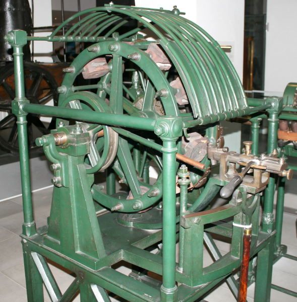
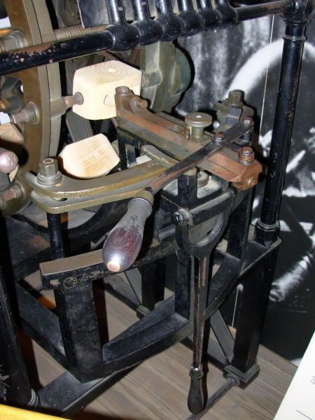
After slotting and having their corners cut off, the elm blocks needed to have their faces made curved. This was done in the shaping machine. There were different radii for the front/back faces compared with the sides.

In principle the machine can be thought of a lathe with a radius turning attachment. However, instead of turning just one component, 10 blocks were clamped in the machine. One face of each was machined at a time.

All the blocks in the 'chuck' were then simultaneously rotated through 90 degrees, and the next face machined, and so on. The cage above the machine is to protect the operator from dislodged blocks.

The distance between the two big wheels of the chuck could be altered to suit different block sizes.

The blocks were located in the clamps using the register marks formed earlier in the boring machine. Rotation of the blocks through 90 degrees was done by gearing - worm and wheel at the clamp position, bevel gears at the other end. The gear ratios were such that by temporarily locking the crown wheel to the machine’s frame, and then rotating the big workholding chuck four revolutions by hand, the blocks all turned through 90 degrees.

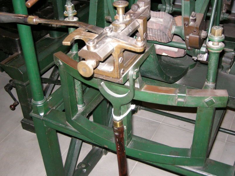
The toolholding frame turns on a fixed radius, but the actual radius at which the tool cuts is set by the cross slide. Now comes an interesting part. I was puzzled by the arrangement on the Science Museum machine and it was only when I looked at my Portsmouth photos (the black machine) that I realised that something was missing. Referring to S2 and the closer view S4, we see that there two brass templates, one above the other. In S2 and the blurred photo S5 you can just see a roller. This is fixed to the underside of the cross slide and is pressed by a hand lever into contact with the template. The two different templates are for the two different face radii on the blocks. There would be different templates for different sizes of block. The roller is raised or lowered by a brass knob to suit the upper or lower template. A clip is swung into position to hold it at the upper level. This can be seen in S3.

Note that the cross slide ways are different on the Portsmouth and Science Museum examples.

The big lever is turned by hand to sweep the tool against the rotating blocks.

Photo S6 shows the bevel gears and wormgear housings, and the drive pulley.

There is a band brake, visible in photo S1.
 
What does the cutter of the shaper look like? Were the blocks stationary while being cut or rotating?

According to the Machinery's Handbook the maximum safe speed for a 6 1/2' flywheel is 258 RPM, they were running that machine more than 50 percent faster, that would be scary. The whole machine would have had to been well balanced for that.
 
great stuff! iirc a few Model Engineer magazine ran a long series on block making machines a few (10 - 20?) years ago
 
something else to wonder about - what was the life of tooling, what was the lubrication interval, what was the timing and effort to remove chips and dust? we know in modern cnc machines, or in manual production shops, that you have to clean stuff out, sharpen or replace tools, and so forth...

also, all of these were line-shaft powered, right? waterwheel? steam engine?
 
In response to questions:

The shaping machine cutters are round hollow gouges. The ten blocks are fixed stationary in the big chuck, which whirls round to carry the blocks against the cutter. The blocks are only rotated relative to the chuck when indexing them 90 degrees to present the next face.

Mortising machine speed – I'm more convinced by the 110-150 strokes per minute mentioned in the 1854 Cyclopaedia than the 400 strokes per minute, which so far I’ve traced back to 1835 and the writings of the of one Dr Olanthius Gregory. I'll leave this and the matter of lineshafts in abeyance pending receipt of a book about the block mills, expected daily.

Power for the mill and other workshops came from two steam engines of about 30 HP, one by Boulton & Watt, the other by Fenton, Murray & Wood.

Cleaning, etc: From the 1854 Cyclopaedia: '…an attention to neatness in appearance of machinery has its advantages, by inducing the workmen to be careful of the machines they work at, to preserve them from the slightest injury, and to keep them clean from dust, which, trifling as it may appear, is a very essential point in the preservation of those parts which are in rapid motion, with friction against other parts, for dust getting between such surfaces grinds them away very fast, and in their most essential points.'

As I was typing this post, the postman delivered 'The Portsmouth Block Mills' by Jonathan Coad, English Heritage, 2005. Despite its recent date, I hadn't previously found a copy at a reasonable price. It's only 127 pages long, but a quick flick through shows that it's packed with good stuff, including illustrations of machines which I thought had passed without adequate record.

One snippet that caught my eye concerned lighting. There was naturally great concern about the fire hazard, but by 1805 an acceptable type of lantern had been obtained which allowed production to be continued in the hours of darkness.

More in due course.
 
Last edited:
Amazing stuff,thank you! I never know which I like more, learning more about machines, or learning that there is yet another machine I didn't know about
 
Many designers today forget what could be done with cams. Take a look at a book of ingenious mechanisms for some down right eye-opening designs that did what we now need a computer to do nowadays.

Thanks for presenting the blockmaking machinery!
 
Coad's Book

The library at the school where I worked had a copy of Coad's book on the blockmaking machinery. It is a great read and covers a lot of information about how the machines were designed and used. It's been a while since I read it and I don't remember all the details. I believe it also goes into a lot of detail about the Portsmouth dockyard as well. It does have information on the steam engines used to power the yard.

If you are close to an engineering school you might be able to find a copy and borrow it through an inter-library loan with your local library. A good place to start looking is:

WorldCat.org: The World's Largest Library Catalog

You can specify your location and find libraries that have the book you are looking for.

Once again I really appreciate the efforts of people like Asquith and Lathefan for the information they post. One of the main reasons I follow this forum.

Thanks again,

Terry


Back
Top