What's new
What's new

Successful Miller CP300 Welder Haas-Kamp Single Phase Conversion

ksimolo

Aluminum
Joined
May 23, 2010
Location
NY, USA
I am in no way qualified to come up with this idea. This conversion worked wonderfully and I owe it all to the information that David Kamp gave on the Practical Machinist web site and in emails to me.

I highly recommend you read through these useful links:

http://www.practicalmachinist.com/v...ler-cp200-converted-240v-single-phase-199832/

http://pounceatron.dreamhosters.com/docs/misc/CP-200_Single-Phase_Step-By-Step.pdf

I can not stress enough to read everything he writes and pay atention to the wiring diagrams and the actual wiring of the machine. If ANYTHING is different, you need to stop and figure out what changes you need to make to the procedures. Insert normal disclaimers here: You are working with electricity. If you do not know what you are doing or make a mistake, you could burn down your building or injure/kill yourself. Make sure you understand what you are doing, take appropriate precautions, and do not rely upon the information published here. What follows is what I did. I make no claim that you should attempt this nor that it is safe to do so. Use at your own risk.

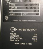
Here is my machine. Please note the face plate specifications and the wiring diagram.
 

Attachments

  • Front of Machine_5884.jpg
    Front of Machine_5884.jpg
    90.9 KB · Views: 5,568
  • Faceplate_5886.jpg
    Faceplate_5886.jpg
    92.3 KB · Views: 2,823
  • Wiring Diagram_5902.jpg
    Wiring Diagram_5902.jpg
    93.6 KB · Views: 29,037
  • Complete Conversion_5951.jpg
    Complete Conversion_5951.jpg
    91.2 KB · Views: 3,888
  • Cover Off and Cleaned_5916.jpg
    Cover Off and Cleaned_5916.jpg
    92 KB · Views: 7,149
From Dave's instructions:

First, find the three main incoming power terminals... that'd be lower right hand side of the main terminal block.

Find wire #5. Label that terminal "C".

Label terminal connected to #6 as "B"

Label terminal connected to #7 as "A".

One difference from Dave's Instructions is that my unit has a dedicated ground.

Find Wire #8... it's one of the three at the main power switch. Follow it to the main terminal block. Label it number 2. Label the REST of the terminals on the BIG strip.

On my machine, the numbering started at the bottom:
Labeled Terminal Board_5924.jpg
 
For the next set of steps, I am going to list them in a different way than Dave sent. First, I did all of the work on the back of the terminal strip, then I did the front.

You can see in the picture above that there are two mounting bolts for the terminal strip. Temporarily remove those. Be careful when bending the terminal strip to get to the back. There are lots of solid wires attached to the strip and you do not want to break those wires. I used a very long socket extension to access many of the terminal nuts. Naturally, all of the wires that I needed to remove had additional connectors bolted on top of them. So temporarily remove the outer wire and then remove the desired wire and put the temporarily removed connector back and reinstall the nut. These are brass so do not over tighten.

Back of the Terminal Strip:

Remove Wire 9 from Terminal 8 and tape it (I used friction electrical tape covered by standard electrical tape). Wire 1 had to be temporarily moved in order to remove Wire 9

There are two jumper wires attached to terminal 11. One goes to 5 and one goes to 17. Remove the 5 to 11 jumper and remove the 11 to 17 jumper.

Disconnect the Fan Wires 20 and 40 from the terminal strip. On mine, they were connected to terminals #3 and #9. Push them out of the way for now. They will be remounted at a later time. Here are pictures showing the fan wires on mine (the screwdriver is pointing to them as I trace them):
Fan Wires 1_5925.jpgFan Wires 2_5926.jpgFan Wires 3_5927.jpgFan Wires 4_5928.jpg
 
Reinstall the Terminal Strip mounting bolts. We are now ready to work on the front of the terminal strip.

Front of the Terminal Strip:

I wanted 130 uf run capacitors but I could not find any at a reasonable price. Instead, I bought a bunch of 65 uF 440V run capacitors - I hooked up 2 of these in parallel for each 130 uf capacitor needed (the rough length of wire required for each capacitor jumper was 5 1/4" before stripping. I did solder bleed resistors (15K Ohm, 5 Watt) between the two pairs of terminals on the capacitor to play it extra safe. I then mounted one of each pair to the back panel with a rubber coated wrap around clamp. The second capacitor was tie wrapped to the first. That can be seen in this picture:

Bus_Caps_5957-2.jpg
 
Connect a Blue wire to Terminal #8. The other end goes to one of the capacitors.

Connect two Red Wires to Terminal #5. One goes to Terminal #14. The second goes to one of the capacitors.

Connect a Blue Wire to Terminal #11. The other end is connected to the other capacitor.

Connect two Black Wires to Terminal #2. Connect one to Terminal #17. The second goes to the other set of capacitors.

To summarize the capacitor wiring, one set of capacitors has a Blue wire and a Red wire. THe other set of capacitors has a Blue wire and a Black wire.

The voltage jumpers should be in the 480V locations which are 3-4, 9-10, and 15-16. On my welder, they were already jumpered for 480V.

Connect the two fan wires to the terminal board, one to a Red terminal and the other to a Black terminal. In my case, I used Terminals #14 and #17.

On the secondary side, remove and tape the three large leads connected to the output contactor. As Dave recommended, I made a shorting bar out of 3/4" copper pipe. Install that in place of the 3 leads. Shown in the picture above.

Connect the 240V power cord with Black to Termianl A, Red to Terminal C, and Green to the dedicated ground GND on the floor of the case. Terminal B is left blank. The power cord I used was 3 conductor plus ground so I taped the end of the white wire and left it.

The final wiring is shown in these pictures:
Complete Conversion_5951.jpgUpper Panel_5952.jpgLower Panel_5954.jpgPower2_5950.jpg
 
I powered it up and the fan came on with no smoke. Then I unplugged it, put the enclosure back together, connected the wire feeder and tried laying some bead. The welder worked wonderfully. Thank you Dave and Peter!!!!

Ken

PS For right now at least, this post can be found at ksimolo.com/CP300 with higher resolution pictures.
 
Thanks to Dave the conversion of my old Miller CP 300 from 3 phase to single phase 240 was pretty easy. The most important thing is to check the schematics of all the wiring. I discontinued wires instead of cutting the, and did all of my connections on the back side of the terminal strip to keep a clean look. A couple of electricians said it would never work. Showed them the results, and they could not beleive the welds that it produced. Made believers out of them. Thanks again to Dave Kamp for all his help.
 
I know this is an old post, but has anyone had the trouble of running too hot? I did mine following the build, but it seems like 1/8" is the thinnest I can weld with mine. Even then it still has signs of being a bit hot.
 
What does this conversion do? does it bypass 1/3 of the input coils. Does it derate the output by 1/3. Seems like used medium size three phase welders are cheaper since home owners can not use them without knowing about this conversion.
Bill D.
 
What does this conversion do? does it bypass 1/3 of the input coils. Does it derate the output by 1/3. Seems like used medium size three phase welders are cheaper since home owners can not use them without knowing about this conversion.
Bill D.
The easiest way is to hit the link to the pdf on the first post in this thread. Goes into detail about what exactly it does. Not a noticable power loss.
 
my name has never been mentioned in the same shop as the word welder - much less the same county.....
however i did run across a real sweetheart of a deal where i work. I was able to buy for scrap price a CP300 with S62 miller feeder.
i tried the conversion but need to ask some questions from the guys who did it the first few times. Where do I find Them?
 
Hi Razz,

You said 430 Volts. I think you want it on 230 volts, not 460 volts. Did you mean 230 or 460? Are your electrical diagrams the same as mine? And you do need to trace the wires to see how they are connected on the terminal strip. Dave's system started at the top of the strip for numbering. On mine, the equivalent numbering started at the bottom of the strip.

Ken
 
Reinstall the Terminal Strip mounting bolts. We are now ready to work on the front of the terminal strip.

Front of the Terminal Strip:

I wanted 130 uf run capacitors but I could not find any at a reasonable price. Instead, I bought a bunch of 65 uF 440V run capacitors - I hooked up 2 of these in parallel for each 130 uf capacitor needed (the rough length of wire required for each capacitor jumper was 5 1/4" before stripping. I did solder bleed resistors (15K Ohm, 5 Watt) between the two pairs of terminals on the capacitor to play it extra safe. I then mounted one of each pair to the back panel with a rubber coated wrap around clamp. The second capacitor was tie wrapped to the first. That can be seen in this picture:

View attachment 81511

I have a question for you. Can you post a link to some reasonable inexpensive resistors?? I found some on Ebay, and coming from china package of 10 shipped to my door from China is $8.00.


Back
Top