What's new
What's new

OT Hydraulic jib crane photo

Ruston3w

Cast Iron
Joined
Dec 20, 2012
Location
Suffolk, England
Hello, I've been gathering photos and also some bits (pump and accumulator) in the hope of finding one of these cranes...no luck yet!
I thought i'd share this one as I was puzzling over how they moved the crab in two directions with a single hydraulic cylinder? I'm guessing it must have used a weight on the return line suspended on the pillar? Presumably the middle cylinder may be slew via chain rather like an early steam shovel?filename-1hydraulic crane.jpg
Richard
 
There _may_ be FOUR hydraulic cylinders on that crane. Two on the "back" diagonal on the right, and perhaps two of the same size on the column.

The second cylinder on the column is behind the obvious one. This second cylinder is extended. It's also darker in color.

Hard to say for sure what that is behind the obvious vertical cylinder on the column. If it is a second cylinder, there's your answer.
 
I guess.. but then you would have to allow one cylinder to "release" at the same time as filling the other? otherwise may end up with a few problems? why make it complicated with lots of linkages...though that leaves at least one spare cylinder, hence I was puzzled.

Richard
 
I think SouthBend is correct ,note that one of those vertical cylinders is fully retracted the other fully extended and the crab is at the far end of the boom ,there seems to be a bit of slack in the wire on the extended cylinder. It is still beyond me exactly how it all works, were these kind of cranes common? never seen anything like it before.
 
I almost didn't open this, because of course modern hydraulic cranes are common. Glad I did, since it's one of the most bizarre machines I've ever seen.

The whole structure looks rigid, except for the truck. So I would expect this to have only up-down and in-out. (Maybe it's on a turn table we can't see?)

But then why so many cylinders? Could they all be single acting, so you need two cylinder to push something 2 directions?
Wouldn't one expect to be able to swing it on its base? But how?
 
Interesting design. I assume the biggest cylinder is doing the lifting, one moves the bogie and one of the middle pair probably rotating the whole structure.
 
Looking at how large the rams are vs the diameter of the cylinders, I'd say they were single acting (displacement) cylinder.

The two slewing cylinders must be tied together. I'm too tired and worried about grades, walking into a truck mirror disnt help, to figure out how the valving would would work. Shame there isn't a picture showing the base.

Sure is a neat mechanism.
 
The cylinders would be single acting,and a good chance using water with soluble oil.The crab can use the pull on the lift line for movement one way,and hyd cyl pull to oppose that.The railway workshop at Ipswich had an extensive water hydraulic system,for cranes ,lifts ,presses,benders etc.The system had a huge hydraulic accumulator which rose and fell to store pressurized water.Some of the rivetters used water pressure too.
 
I turns, there is a pivot up top that appears to be connected to the building steel. There is a diagonal brace visible, and presumably a matching one on the other side behind the crane.

It almost looks as if the cylinders might be 'shuttle pistons", where the rod goes right through with a piston in the middle, one end pulls in and the other lets out, at the same time.
 
I think there is indeed another smaller clyinder on the back side of the diagonal. Looks to be two lines on each side of the vertical that run the trolley back and forth. The other would be fully collapsed to run the trolley out. I do agree the vertical cylinders must be the rotation mechanism, as it appears to be swung to the limit., would swing the other way with the cylinders in the opposite positions.
 
I'm afraid I haven't presented the best picture for scrutiny, my scanning/uploading lacks finesse , looking at the original with a lens gives a few clues.
I think you can see a diagonal rope leaving the smaller inclined cylinder from the fixed sheave towards the lower swing bearing, this must be single acting and matched the other side for slewing?
The two vertical cylinders both run up to the right place on the jib to be powering the traverse ,one pulling either way.
Water -hydraulic of course, not sure if they ever added oil? Next door here we had a factory running remote water and oil accumulator systems for press work and running lifts(hoist).
The high pressure system was multiplied up to power Henry Berry (Leeds)filter presses. I think the system ran at 10,000psi, the presses had 9" cylinders, pressing cellulose through fine brass gauze with filter cloth over them, I think the press cylinder ran at 15,000psi.
The water system ran at much lower pressure with lots of "old fashioned" fits, leaks and much of the system direct to waste.A friend of mine worked there from the early '60s, maybe '63 was a cold winter, the water accumulator drive pipe froze one night between shifts, when they started fiddling to workout what was the problem it blew the frozen fitting off together with a plug of ice, the tank fell to the ground showering freezing water, landed on the railway sleeper (ties?)table used to rest the tank on when down. The tank held 30tons of sand and was made of 5/8" rolled plate, all bolted up with 5/8 Bolts. As the tank landed each row of bolts sheared in turn,
leaving a kit form accumulator. As my mate tells the story the whole place shook, windows broken ,etc. Funny really, 130 yrs of working with nitro-cellulose and similar and the biggest bang was a tank full of sand!

Richard
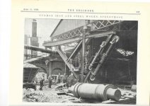
 
The article describing the crane is here:-

https://www.gracesguide.co.uk/Special:MemberUsers?file=8/80/Er18930421.pdf

You have to sign up (free) to read it, but there's nothing sinister about that.

Five single-acting W. Armstrong-type rams:-

One 12" for lifting
Two @ 6" for racking
Two @ 8" for slewing (wire rope takes several turns round a horizontal drum below the floor). The wire rope has spring-loaded toggles to absorb shock when slewing suddenly stops.
 
The rams were a trap for young players too...water would leak past the pistons under load,and when the ram ran out to the end of the stroke,stinking water would squirt out all over anyone not familiar with the gear.A poor apprentice soaked with water that smelt like sewage first thing on a cold morning.


Back
Top