What's new
What's new

What would be the best kind of machine for this sort of work?

PCar73

Aluminum
Joined
Jan 6, 2019
Hello,

I am new here. My company is beginning to make reproduction Porsche 911 engine cases, and the way we are doing it is by having the foundry make the casting (A356T56), then using our Haas UMC 1000 to machine the features within the case halves. We have this part pretty much figured out.


What the problem is, or the part we can't wrap our heads around is how to properly ream/bore/drill the main journals and layshaft accurately.

The way this SHOULD be done is to bolt both the case halves together and align bore both the mains and the layshaft. This part we know. HOWEVER, what would be the best machine to do this with? Specs are as follows:

Main journal bore: 65.000-65.0019mm - approximately 20.5" long
Layshaft bore: 27.500-27.521 - approximately 20.5" long

No one has built a new case in decades, and the knowledge of how to do this seems lost. In the aftermarket, when repairing an old case, usually all that is needed is a line hone. In this case, we have to establish the initial rough bore with the UMC 1000, and then create a finished bore.

I was thinking a Jig Bore would be best for this, but I haven't yet seen one that has 20.5" of Y axis travel yet.

We need these two parallel bores to be ultra accurate, but the good news is, once we set up and fixture this operation, we will be able to do it over and over again. We are only making the one case.

86286d1379552128-porsche-911-engine-machine-work-deckel-110.jpg86378d1379633744-porsche-911-engine-machine-work-deckel-178.jpg86381d1379636321-porsche-911-engine-machine-work-deckel-183.jpg 
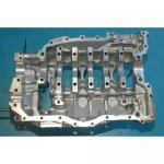
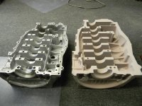
(NOT MINE), of someone on this forum doing a repair operation on a used case that gives an idea of what we are looking at.

Thanks for your help!!!!
 
In this pic you can see the crank in the split case half - this is the main bore I am talking about. In the upper left, you can see the layshaft bore - it is a small / short bore.Restoration+0521279248264.jpg
 

Attachments

  • 3275_7-500x500.jpg
    3275_7-500x500.jpg
    46.5 KB · Views: 476
  • DSCN3436.jpg
    DSCN3436.jpg
    94.1 KB · Views: 467
Originally I am sure it was a huge single purpose horizontal boring machine that did the whole operation a 10 seconds.

Otherwise I don't know how you get that bore as straight as needed.

There must be automotive line boring machines around, I don't think honing is designed to make it straight
 
Originally I am sure it was a huge single purpose horizontal boring machine that did the whole operation a 10 seconds.

Otherwise I don't know how you get that bore as straight as needed.

There must be automotive line boring machines around, I don't think honing is designed to make it straight

I am also sure of the same thing, because Porsche made hundreds of thousands of these from 1965-1996, with various bore sizes.

Lots of automotive line boring machines by Rottler and Sunnen - VERY FEW if any that can accommodate a split case design. Most are for engine blocks, not engine cases.
 
Line boring (not honing) engine blocks is done all time. I don't know the best machine for the job but I'm sure a few phone calls could turn up some names of makers. The 20.5" length you need is not unusual and I'm sure the average line boring machine could do it.

My compliments on your thread...it's actually a well versed post, has good photos, and is an interesting topic.
 
Thank you!

What I have found is that engine BLOCK line boring is done all the time with a variety of machines. Most of these machines are meant only for traditional blocks where one can fit a boring bar in the mains, bolt on the caps, then have at it. Berco, Sunnen, and Rottler make machines that do this, but exactly NONE of them work on an engine CASE where the mains are concealed by the case itself, and there is no way to use the support bars that hold the boring bar straight.

This is why I want to pick the collective brain trust's head to see if there is an older, more primitive solution to this. As I said before, a Jig Bore machine with enough travel would be perfect to bore a long, straight hole.

I will make sure that the UMC 1000 removes as much material as possible so that the line bore doesn't have to work very hard at all.

It's quite a conundrum for me....
 
Here is a typical align bore machine. Everyone and their dog makes one. As you can see, all that is required to align bore the block is to place the block in the cradle, place the boring bar in the journal, and bolt on the main caps.

To do this with a case, you would have to bolt the case together around the boring bar, which would take much longer.

The real issue for me is not that I can't adapt a typical boring machine to work; it would just take an inordinate amount of time to do each case vs. a dedicated vertical or horizontal solution that could be fixtured up.
 

Attachments

  • lb7000-on-v20.jpg
    lb7000-on-v20.jpg
    88.4 KB · Views: 552
Send a personal message to AlfaGTA who lives mostly in the Deckel area, or post your query there. This is the kind of work he does all the time and with more exotic engines.
 
If machine space isn't terribly limiting, I'd do the mains on a large radial arm drill, either an American or Carlton. It will be a quick operation. Fixturing and tooling will cost more than the machine.

The layshaft can be done in the same fixture.

You have an extra zero in the tolerance for the mains. The layshaft appears shorter than your 20.5 inches. How long it it?
 
You are correct sir. I don't have one in front of me but I'll say the layshaft is 8-9" long.

Wow, that Carlton is a monster. I think we have the room. Can it maintain that accuracy? Sure looks like it based on the bulk!
 
Possibly start hunting around the motorcycle engine production world for inspiration.

Most multi-cylinder motorcycle engines use horizontally split cases albeit with the block cast integral with the upper half but it's still the same basic layout with bearing seats in the closed off lower case / sump unit.

Clive.
 
A radial arm drill won't provide the accuracy, it will just drive the boring bar. The accuracy is in the bar and fixturing.

A horizontal boring mill could also do the job. Machine costs will be higher, but flexibility will be much greater.

With any method you need to figure on a large tooling bill for the bar.
 
I mean no disrespect since you are obviously not in this class but...This looks like one of those home shop ideas where the case is bolted to a lathe carriage with a large boring bar supported between head and tail stocks. The carriage is slid left to right and the cutter advanced for each pass.
I suppose you could have one cutter at each bore, and every diameter, and do it all in one short stroke.
This would obviously require accurate repeatable registration points on the outside of the case so it could be shifted to cut the other shaft parallel to the main.
Bil lD.
 
SO I am going to think out loud, which is, of course, working without tools.........

I imagine you are going to have each case laid on a VMC table to machine the mating surface, bolt holes, location dowels, oil holes and various other details.

What if you interpolated the bearing bore with and YZ interpolation and a ball end mill.

Would you be able to get it close enough to hone?

IT is certainly not a high production method, but hundreds is not really high production

I am thinking you might want something better than a HAAS

I am thinking you are going to need high end inspection both on the machine and off the machine.

Like custom gauges and straightness gauges to check on machine and a good CMM off the machine

Let's face it, the whole thing is defined by the location of the location dowels in the case halves. I am assuming they have location dowels.

I don't think I am wrong in saying that you are fooling yourself with any tolerance greater than the tolerance on the assembly points.

I mean the going assumption is that you bore after assembly because there is no way to locate them accurately in a second op, but if it was possible to eliminate the second op....

I am probably completely off base, but that is the thought that occurred to me.
 
I mean no disrespect since you are obviously not in this class but...This looks like one of those home shop ideas where the case is bolted to a lathe carriage with a large boring bar supported between head and tail stocks. The carriage is slid left to right and the cutter advanced for each pass.

Home shop guys use this idea, but I first saw it done by the builder of superchargers. A major supplier of blowers to TF cars did their 14/71 cases this way. The lathe dedicated to the job was smaller and cheaper than a boring mill and they only did one size of bore over and over so they didn't need a more versatile boring machine. This also allowed them to use a large diameter bar to reduce deflection. They made a fixture for the top of the cross slide to hold the case, and used the cross slide to position the 2 bores.


Back
Top