What's new
What's new

Need help identifying Historic Machine/Process

Fal Grunt

Titanium
Joined
Aug 5, 2010
Location
Medina OH
I have a part I am making for a customer that I am frankly stumped at how I am going to machine a feature, let alone how it was machined originally. Part was manufactured in production in the 1920's.

Part has in inside pocket, about .376" across, that has a square corner and is along a radius. The tool marks for this feature show a tool that is working or moving along that radius.

Say for example, you had a shaper, and a rotary table, as the shaper advanced, the rotary table advanced to generate the curve.

I tried to take a picture of the original part to show the tool marks, but cannot get a decent picture where the tool marks show up. You have to hold the part just right, and get a reflection, but not direct light, to get the marks to show up.

I have attached pictures of the solid model I made of the part.

Inside Square Corner Radius Broach 2.jpgInside Square Corner Radius Broach.jpg

I am curious what machine historically had the ability to make these cuts?
 
I have seen setups in various old books and magazines on planers set up to produce curved surfaces like those used on locomotive valve gear links .
The part is set up to rock back and forth or from side to side on jig or sub table as the table travels back and forth under the tool.
The radius being controlled by the a linkage to the stationary base of the planer .
Here is a link to one setup that I remember seeing since i have a printed copy of this.
Planer work ; Shaper and slotter work ; Milling-machine work ... - Full View | HathiTrust Digital Library | HathiTrust Digital Library
Here is a similar idea for milling but without having some kind of off set internal fly cutter I don’t think it would apply your situation.
A treatise on milling and milling machines. - Full View | HathiTrust Digital Library | HathiTrust Digital Library
The movement principal is still the same so on a shaper you would have to co- ordinate the rocking or oscillation with the ram .
If you could post a picture of the overall part with out worrying about seeing the tool marks it might be easier for others to offer suggestion .
Perhaps a coating from a felt marker that can be wiped off with methyl hydrate or other solvent would help reduce the glare in the pictures.

There may be some examples for a shaper in this thread
https://www.practicalmachinist.com/...ies-152439/index28.html?highlight=Shaper+Work
Its quite long but there are some examples of un common shaper set ups posted there .
Here is one I posted a while ago and I think there are other similar articles linked there too.
Machinery

Regards,
Jim
 
Illinoyance ‘s post reminded me of another setup I had seen in an old book or magazine perhaps a Popular Mechanics Shop Notes where a lathe head stock was was made to oscillate back and forth with an arm connected to the face plate driven by a crank disk but could have been done by hand as well.
There was some discussion about a similar setup although for a convex surface in this thread although I didn’t find the exact link I was thinking of for the lathe setup.
Steam engine part – How machined?
I posted links in post #43
There is another planer setup shown here too.
The railroad and engineering journal

Again without seeing the overall design of your compete part we can’t tell what may interfere with the cutting action .
If it a one of part, the time to build a special jig would probably make rocking a lathe chuck , rotary table on a mill or other setup back and forth by hand a more suitable option .
Jim
P.S One more here a couple of pages farther down
The railroad and engineering journal
 
Last edited:
If you could post a picture of the overall part with out worrying about seeing the tool marks it might be easier for others to offer suggestion

Again without seeing the overall design of your compete part we can’t tell what may interfere with the cutting action .

Jim,

Thank you for the excellent posts and references! Some great ideas, and it gives me a few ideas to continue looking.

Unfortunately the customer does not want the assembly pictured on the internet. The first picture above shows either side of the 3/8" slot that is about an 1" long.

This eliminates any lathe type of tool that I could imagine.

Thanks again for your posts!
 
The first picture above shows either side of the 3/8" slot that is about an 1" long.

And it shows a white area in between - do we assume the white area is OPEN allowing cutting tool to pass thru?

How does that relate to second picture - which appears to be blind?

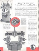
If photo 1 applies, a shaper tool in a P&W profiler (your muscles make the movements - and tool is guided by a template) would do just fine

Lots and lots of these machines went to armament factories - from about the 1870s on

Scans from 1945
 

Attachments

  • Scan 01_1.jpg
    Scan 01_1.jpg
    97.2 KB · Views: 159
  • Scan 01_2.jpg
    Scan 01_2.jpg
    93.8 KB · Views: 135
And it shows a white area in between - do we assume the white area is OPEN allowing cutting tool to pass thru?

How does that relate to second picture - which appears to be blind?

If photo 1 applies, a shaper tool in a P&W profiler (your muscles make the movements - and tool is guided by a template) would do just fine

Lots and lots of these machines went to armament factories - from about the 1870s on

Scans from 1945

Picture 1 is the picture of the slot from the top. It shows the two radii.

Picture 2 is the bottom of the two radii, zoomed in and the part tilted slightly so you can see the tedious better.

Maybe this analogy will help explain what it looks like. Take a small match box and look at the end profile so that you can see the rectangular profile of the outside cover and inside box. Slide the inside box out. If you hold the thin section horizontal you have the inside shape of the part, just imagine the 9 o’clock wall is the curved surface pictured above.
 
Agree with Mr. Oder....single point tool traveling on a radius matching the radius of the part...if that makes sense...I suck at explanations.
 
I have a part I am making for a customer that I am frankly stumped at how I am going to machine a feature, let alone how it was machined originally. Part was manufactured in production in the 1920's.

Part has in inside pocket, about .376" across, that has a square corner and is along a radius. The tool marks for this feature show a tool that is working or moving along that radius.

Say for example, you had a shaper, and a rotary table, as the shaper advanced, the rotary table advanced to generate the curve.

I tried to take a picture of the original part to show the tool marks, but cannot get a decent picture where the tool marks show up. You have to hold the part just right, and get a reflection, but not direct light, to get the marks to show up.

I have attached pictures of the solid model I made of the part.

View attachment 262399View attachment 262398

I am curious what machine historically had the ability to make these cuts?

Tool marks or no, a picture or three of the "real" component would help.

Looking for overall size and how close to final a casting or forging started with so as to grok how heavy a cut was needed to deliver the curve.

Suspect it was done with a dirt-common machine tool, just an unusual workholding concept.

That, too, was once "common as dirt" .... out of far greater necessity and lower burdened cost of skilled time to build the tooling.
 
I doubt you'll get any definite answers without showing the part. We can guess at ideas but the extreme close up drawings provided don't show enough context to know for sure.
 
As mentioned, a blind cut to a solid bottom would be very difficult and, as mentioned, tedius at best, edm maybe?

1920's? Could be an 1880's design, then. EDM not likely.

My bet is simple, not complex. Engine Lathe... HBL, VBL, HBM, VBM. Basic Mill with boring head....

We just need actual pictures so we can rotate 'em in our own heads.

Not "solid models" generated by a high-speed idiot. The computer. Not the user.
 
I have a part I am making for a customer that I am frankly stumped at how I am going to machine a feature, let alone how it was machined originally. Part was manufactured in production in the 1920's.

Part has in inside pocket, about .376" across, that has a square corner and is along a radius. The tool marks for this feature show a tool that is working or moving along that radius.

Say for example, you had a shaper, and a rotary table, as the shaper advanced, the rotary table advanced to generate the curve.

I tried to take a picture of the original part to show the tool marks, but cannot get a decent picture where the tool marks show up. You have to hold the part just right, and get a reflection, but not direct light, to get the marks to show up.

I have attached pictures of the solid model I made of the part.

View attachment 262399View attachment 262398

I am curious what machine historically had the ability to make these cuts?

Might have been done on a vertical slotter.

lookup Buttler

dee
;-D
 
Tool marks or no, a picture or three of the "real" component would help.

Looking for overall size and how close to final a casting or forging started with so as to grok how heavy a cut was needed to deliver the curve.

Suspect it was done with a dirt-common machine tool, just an unusual workholding concept.

That, too, was once "common as dirt" .... out of far greater necessity and lower burdened cost of skilled time to build the tooling.

I doubt it was a "common as dirt" machine, unless it was a setup with a very uncommon attachment or in a very uncommon way. I own most of the "common as dirt" machines available ranging from 1895 all the way to 2018.

I'll leave you to your grok'ing, whatever that is.

I doubt you'll get any definite answers without showing the part. We can guess at ideas but the extreme close up drawings provided don't show enough context to know for sure.

Guess away... as I said... customer said no.

As mentioned, a blind cut to a solid bottom would be very difficult and, as mentioned, tedius at best, edm maybe?

A sinker would work, cut the radius form and feed in from the other side of the pocket. Definitely tedious and not very production friendly.

1920's? Could be an 1880's design, then. EDM not likely.

My bet is simple, not complex. Engine Lathe... HBL, VBL, HBM, VBM. Basic Mill with boring head....

We just need actual pictures so we can rotate 'em in our own heads.

Not "solid models" generated by a high-speed idiot. The computer. Not the user.

I do not think it is anything too complex, but I do not think simple either.

In a catalog I recently found a horizontal mill that was a production machine, could be used for gears, endmills, anything that needed indexed and cut. The dividing head was setup to the machine, so that at the end of each cut, the machine would return the tool to zero, move the table back to zero, rotate the dividing head, engage the cutter and feed to the end of the cut, through the roughing and finishing passes. All off of 1 belt driven motor. That was in 1901. Pretty simple by today's standards, damn complex in my opinion. I'm guessing it is in between the two.

Might have been done on a vertical slotter.

lookup Buttler

dee
;-D

To me it looks to be a single point tool, and a vertical slotter or shaper, with some form of attachment to rotate the part during the cut seems the most likely to me. It is certainly going to be an interesting job!
 
Sorry this is so vague, in one of the 1920's 30's machine tool books, maybe one by Colvin and Stanley was an image of work on a universal shaper that seemed to approximate what you need to produce. Might have been a book from ATS?


Back
Top