What's new
What's new

Difficulty in understanding schematic symbol

That seems to be the case, although it would not be standard in my world......

Some of them, labeled "RT" and a number, have contacts shown elsewhere on the schematic.
 
Agree that was definitely indicated for some, but others, well they just don't seem to fit, like the one the OP asked about.

I've seen that in really ancient schematics, like from the 1930s, where resistors were rectangular blocks, and coils were zig-zag like that.
 
I'd agree that zig-zags 6, 6A, 6I, and 6P are the coils for the relays whose contacts are marked 6, 6A, 6I and 6P.

I think 6EM is a control relay to convert a momentary pushbutton contact into a sustained "on", with a side order of EMergency stop functionality, but I think it's sort of bad practice to combine emergency stop with pushbutton sustain that way.
 
you can't mistake one for the other, resistor rectangle is always skinny with wires coming to the narrow ends, relay rectangle is fat and wires connect to the long sides

as for the OP, it seems to be thermal/overload protection, once the 2 are open, the 3rd wire will not be connected to anything so no current can flow and doesn't need protection on it:
thermal-prot.JPG

edit, I was wrong, not thermal, but seems to be something like NC relay contacts

edit2, another description:
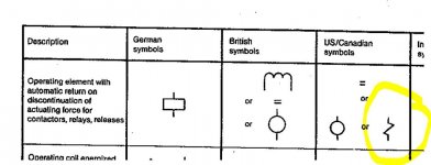
zigzag.JPG

edit3, found another one, still under US/CAN symbols - magnetic overcurrent relay, so overcurrent breaks the NC contact presumably

https://forums.autodesk.com/autodesk/attachments/autodesk/38/16780/1/HOW%20TO%20READ%20DIN%20(GERMAN)%20DIAGRAMS.pdf
 
The machine is Italian from the mid 70's. I am beginning to think that the schematics are not for this machine.

Very few of the wire numbers on machine match the schematics. 66# and 67# do match and they go to the E-stop (6EM) button.

I'm wondering if the RT designate heaters as the RT1, RT2 seem to match the two remotely mounted heaters, middle, far right. The output of them is U and V respectively.

Coils for starters are 120v.

Large starter at bottom is for the spindle and oil pump. Starters above that are rapid forward, rapid reverse,and coolant pump. To the right of them is a 4 pole single throw relay.

The large starter only has 2 heaters. Seems a bit odd to me.

DSCF1073.jpg
 
they would be more like modern resettable fuses, they have 2 components in them - a thermal and magnetic, thermal will trip on light/long overload, magnetic will actuate instantly and disconnect the circuit - and that is what you have marked as RT1 through RT4, not sure how it looks physically, but the way they work is - unless they are tripped, they stay closed, and if there is a short in the circuit (motor coil insulation failure for instance), it will create an instant overload > and the electromagnetic actuator will break the circuit, it is necessary only on 2 of the 3 phases, since when you break 2 of the 3 wires coming to that motor - no current can flow

p.s. red box around the part we were discussing in the other thread, FR being the mystery device, and if it is, then you indeed had an error in your drawing or the wiring has been altered, you had the top wire going to "0" loop back on the NO 6EM contacts, when it should have went back to the transformer like I suggested never mind this - I see that it goes back to "0" via another 6EM contact group
Capture.JPG
 
they would be more like modern resettable fuses, they have 2 components in them - a thermal and magnetic, thermal will trip on light/long overload, magnetic will actuate instantly and disconnect the circuit - and that is what you have marked as RT1 through RT4, not sure how it looks physically, but the way they work is - unless they are tripped, they stay closed, and if there is a short in the circuit (motor coil insulation failure for instance), it will create an instant overload > and the electromagnetic actuator will break the circuit, it is necessary only on 2 of the 3 phases, since when you break 2 of the 3 wires coming to that motor - no current can flow

I think we are talking about the same device. In the USA most people refer to the overloads as "heaters"

FWIW, in a previous life I was a licensed industrial/commercial electrician. Some of the symbols in this schematic have thrown me for a loop as they don't look like any that I recall seeing before...
 
The large starter only has 2 heaters. Seems a bit odd to me.
Nah. Adding a third heater would add value only if you expect the heater to be the thing that catches shorts to ground. (And that's not what heaters are for.) Assuming no shorts, any current through the motor has to pass through two of T1/T2/T3. So two heaters are sufficient to catch overload currents.
 
Finally figured out what the zigzag symbol is. Heaters/overload integral to the motor starters, one of which is a NC contact well hidden behind the usual heater assembly.

DSCF1080.jpg

Hidden contact lower left of starter. #3 wire is daisy chained to all the starters.
 
The zig-zags in the POWER circuit would have been the heater elements (coils). The zig-zags in the CONTROL circuit would be the solenoid coils. That's an old European standard prior to the "harmonization" of IEC standards in the late 70s / early 80s. I worked for a German company (Klockner Moeller) at that time, we used those symbols on equipment drawings we made here because "Zat ist de vay you vill do it!", but we were constantly having to explain it to people here in the US.
 
The zig-zags in the POWER circuit would have been the heater elements (coils). The zig-zags in the CONTROL circuit would be the solenoid coils. That's an old European standard prior to the "harmonization" of IEC standards in the late 70s / early 80s. I worked for a German company (Klockner Moeller) at that time, we used those symbols on equipment drawings we made here because "Zat ist de vay you vill do it!", but we were constantly having to explain it to people here in the US.


So, what you are saying is that all the zigzags in the control side of the schemati9cs are the coils in the motor starters?

As I continue to trace wires down, I get more confused. Most of the (few) wire numbers in the schematics do not match the machine numbers.

And all this started because none of the lights on the machine worked when I got the machine. At this point, the only light that works is the 24v on the far left of schematic. It is simply an indicator that the power is on.

319616d1619124815-difficulty-understanding-schematic-symbol-dscf1072.jpg
 
Here is a novel approach.
Act as if you have no schematic or prints, track down wires and draw your own.
Bob


Which I have been doing. Trying to isolate each circuit as i go. Have about 15 pages so far. It hasn't helped that at some point in the past, the wires in the carriage were replaced and a whole new set of numbers attached to the new wires. WTF.

In the schematic above there is a symbol at the bottom of the "rapid motor" that has me puzzled. Symbol is circle with FR in it. Traced the FR wire to the carriage where it disappears into the interior of the apron.


Back
Top