What's new
What's new

Contactor Sizing

Dave Belchamber

Plastic
Joined
Oct 21, 2021
Just received a 1981 1.5 hp Bridgeport and purchased a TECO Westinghouse L510-202-H1-U VFD to drive it. The VFD input will be single phase 220VAC and was sized to accommodate a 2hp 1.5kW three phase 220VAC motor (because the next smallest size was for a 1hp). I'm a newbie at all of this so please bear with me if I make any stupid comments. A simple 'you're wrong about ...' without being flamed will suffice. In any event, the VFD documentation suggests to me that it will draw 15.5 amps, which seems a lot compared to the 4.4 amp rating for the motor, even when taking the single phase versus three phase differences into account. So my first question is whether my understanding of the 15.5 amp draw is correct? Next, I'd like to utilize remote switches for a proper E-stop, Start and Forward/Stop/Reverse (likely repurposing the existing old but high quality motor switch). This suggests that use of a contactor would be appropriate. My investigation to-date suggests a 1.5-2 times safety factor to the power rating of the VFD would be appropriate for sizing the contactor. If that is true, then am I correct in saying the contactor should be capable of handling 220V * 15.5A = 3.4kW * safety factor of say 1.5 = 5.1kW? On this basis a 5.5kW contactor would suffice. I'm also thinking that it would be much safer to utilize 24VDC for the switches, contactor coil and cooling fans (in the power cabinet). Lastly, it would seem logical to have a main power switch that will kill the 120VAC supply to the 24VDC power supply, the X-axis drive and future accessories such as a DRO and work lighting. I'm still working on the details, but clearly there is a lot to think about. Any suggestions/instructions/advice and especially wiring diagrams from those that have gone before would be greatly appreciated.
 
The 15A does not sound far out, our 3HP drew about 26A.

The contactor issue is not or should not be a problem here, because the VFD ought to handle all the control features you mention. You don't want to add contactors for that. Maybe you don't mean that, so apologies if I am over-reacting.

Just use the regular control inputs, setting the thing to use a remote, which would be a series of settings in the parameters. The manual ought to show you just what to do and how to connect it up.

You should have a Fwd/rev switch, a go and stop switch, and a pot to control speed. Those can be located anywhere you want within reason. You will probably want to use multi-wire shielded cable to minimize the chance of surprises, but some setups use 8 wire ethernet type cable.

Generally, you do not want to be cycling power for the VFD very much. Use the controls, an input power switch, and unplug if you need a positive disconnect.

Thanks for confirmation of the input amperage. WRT the contactor, I think you hit the nail on the head. There is no On/Off switch on the VFD so am I correct in assuming that, in the absence of a contactor, the VFD will be in a power on state whenever the input cable is energized? If so, I will either need a wall outlet to enable unplugging the cable, a contactor to safely de-energize the VFD or use the circuit breaker as an On/Off switch (which is clearly a No-No according to the VFD's manual). I'm not keen about having the VFD energized when I'm not in the shop. Leaving the VFD energized seems to be putting a lot of trust in the unit's micro-processor.
 
it's good to be able to turn it off easily if there are thunderstorms. They do not like big spikes on the power very much, although they may survive most such spikes.

It's not as if the VFD is ging to start running the unit randomly. It "could" happen, but is unlikely.
 
Thanks for confirmation of the input amperage. WRT the contactor, I think you hit the nail on the head. There is no On/Off switch on the VFD so am I correct in assuming that, in the absence of a contactor, the VFD will be in a power on state whenever the input cable is energized? If so, I will either need a wall outlet to enable unplugging the cable, a contactor to safely de-energize the VFD or use the circuit breaker as an On/Off switch (which is clearly a No-No according to the VFD's manual). I'm not keen about having the VFD energized when I'm not in the shop. Leaving the VFD energized seems to be putting a lot of trust in the unit's micro-processor.

Do you unplug your microwave or electric range every time you leave the house or go to bed...probably not.

Stuart
 
Do you unplug your microwave or electric range every time you leave the house or go to bed...probably not.

Stuart
Of course not! I have a large knife switch and cut power just past the meter base. It's a real pain resetting all the clocks, though.

Sent by telegraph using - .- .--. .- - .- .-.. -.-
 
Thanks for confirmation of the input amperage. WRT the contactor, I think you hit the nail on the head. There is no On/Off switch on the VFD so am I correct in assuming that, in the absence of a contactor, the VFD will be in a power on state whenever the input cable is energized? If so, I will either need a wall outlet to enable unplugging the cable, a contactor to safely de-energize the VFD or use the circuit breaker as an On/Off switch (which is clearly a No-No according to the VFD's manual). I'm not keen about having the VFD energized when I'm not in the shop. Leaving the VFD energized seems to be putting a lot of trust in the unit's micro-processor.
I wouldn't worry about it. If you ARE going to have a disconnect for the VFD, put an on/off switch adjacent to the VFD and run the power cord through that before the VFD. Having to unplug stuff like that everytime you use it is annoying.


Sent by telegraph using - .- .--. .- - .- .-.. -.-
 
I've had half a dozen drives powered up 24/7 for almost 30 years at my day job, and have 4 drives in my home shop powered 24/7 for 25 years and they have never had a hiccup. They just sit there, waiting for orders from headquarter to run when the button is pushed. No explosions, no fire, no nuttin.

This is not lighting country, if that matters.

Stuart
YOU REBEL!


I've left my MIG on over night... nothing bursted into flames.

Sent by telegraph using - .- .--. .- - .- .-.. -.-
 
Do you unplug your microwave or electric range every time you leave the house or go to bed...probably not.

Stuart


Nope.... But at home I DO unplug a number of things, and shut off some water if we are leaving town for a week or so. The water particularly.... I don't want to come home and find that a hose broke and doused part of the basement.

VFDs, and some computers are on the list to unplug, or hit the disconnect for.
 
If you're using a VFD then why are we talking about power contactors and 120:24V power supplies?

Any* VFD on the market will be equipped out of the box for 240V or 480V power input, 240V or 480V power output and will be fitted with an internal 24VDC control source. Line conductors get landed on the line terminals, load conductors on the load terminals and then you build a 24V control circuit from there. Most drives allow you to wire the control terminals either 'sourcing' or 'sinking' as desired. The nicer ones will allow you to use RS-232 and/or RS-485 as well.

2*746/220 = 6.78 amps single phase in a perfect world. Figuring 70% efficiency, that bumps up to 9.68 amps. A 2 horse single phase motor will generally pull about 12 or 13 due to non-unity power factor. What figure are you looking at which suggests 15.5A? A minimum circuit ampacity or an intermittent rating? I've got a 3 horse single phase input drive that only pulls 12A at full load.


*Yu-Long-Ding-Dong garbage 'drives' notwithstanding.
 
1) you don't need to power the vfd via a contactor. A suitably-sized switch is good. Bonus for correct overcurrent protection like a fuse.

2) do not interpose any switches or contactors between the vfd and the motor. Control and protection are handled by the suitable programming on the drive.

3) read the manual for the drive for parameter setup for your particular motor, and for your desired external control details, if you want to control direction/speed by a means other than the drive keypad.
 
Thanks for the detailed feedback. I'll check into the programmable "Enable" or "Run" aspects. I've read the manual, but clearly didn't understand everything. BTW I do turn off the power to all my 120VAC wood working machines when not in the shop. I have a grand-daughter living in the house and would not want any machine to be accidently activated by a little kid. I like Blondihacks warning that any machine is purposely trying to kill you, so treat them with respect and avoid the anguish.
 
Thanks for the detailed feedback. I'll check into the programmable "Enable" or "Run" aspects. I've read the manual, but clearly didn't understand everything. BTW I do turn off the power to all my 120VAC wood working machines when not in the shop. I have a grand-daughter living in the house and would not want any machine to be accidently activated by a little kid. I like Blondihacks warning that any machine is purposely trying to kill you, so treat them with respect and avoid the anguish.

A lockable disconnnect for all the machines, then is a good idea.

Most VFD users have a remoted contol for thei drives, hardly anyone uses the keypad. The control functions are typically low-voltage lines and are detailed in the manual. You'll need to figure out how to acess the parameter space to set up the low-voltage terminals to make the drive behave as you wish. It sort of like setting a digital watch, only easier.

For my lathe and milling machine, they have a single center-off switch that gives forward and rev spindle, and a small knob that operates a variable resistor for speed control. You can set the high and low speed end-points on the control via the parameters. It's all in the manual, give it a good read.

It's a lot easier when you set up your 2nd or 3rd drive!
 
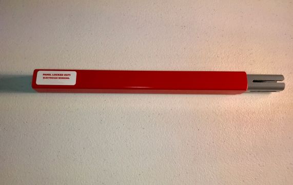
If your shop has it's own sub-panel, you might consider a lockable cover kit or one of these as an easy solution...

Panel%20lockout%20kit%20application%20photo.jpg
 
............................

2*746/220 = 6.78 amps single phase in a perfect world. Figuring 70% efficiency, that bumps up to 9.68 amps. A 2 horse single phase motor will generally pull about 12 or 13 due to non-unity power factor. What figure are you looking at which suggests 15.5A? A minimum circuit ampacity or an intermittent rating? I've got a 3 horse single phase input drive that only pulls 12A at full load.


.........................

The VFD will be far better than 70% efficient.

The problem occurs in rectification from single phase. The pulse current inherent in intermittently filling the capacitor on peaks has a higher rms value than it seems.

The power factor is lower, so non-power current is flowing. That raises the measured current.

How much effect that has depends on the size of the capacitors in the unit, as well as power etc. Plus, all the power must flow in on two wires.

My question to you is "how do you know it is pulling full load?". Presumably you have checked the motor current on all leads and you POSITIVELY KNOW it is at full load current at the time you measure the input?

Perhaps we have found a real life example of Jim Rozen's "amp-clamp problem"? But it is pulling LESS current, while the A-C problem is alleged to read too HIGH a current.:D;)
 
The VFD will be far better than 70% efficient.

Not after accounting for motor losses. Small induction motors are deceptively inefficient. A 1/4 horse 3 phase will do about 65% eff and 0.55 PF. A 2 horse 3 phase probably in the neighborhood of 75-80% eff. Maybe 82-85 if we're talking a NEMA Premium motor (Baldor Super-E, etc.).

Table-12-12-0913.jpg


"how do you know it is pulling full load?"

In my case, the motor was driving a 3 horsepower rated compressor pump at it's maximum rated pressure and speed - verified by tachometer and it's ability to maintain pressure while flowing through a known orifice.

I read 12 amps single phase as measured by a shunt-type magnetic movement.

746*3/220=10.172A

10.172/12= 84.77% efficiency... About what I would expect to see at unity power factor after accounting for a few watts of drive losses. Assuming unity power factor since VFDs inherently correct load-side power factor.

Rectifier-capacitor circuits do pull power in pulses, but they are pulses of real power, not apparent power. 100% of it is eventually put to work. None of it gets returned to the grid at the end of each half-cycle. Therefore VFDs can be said to be high power-factor devices - even if they present very non-linear load characteristics and introduce some harmonics.

20211022_191245.jpg
 
My question to you is "how do you know it is pulling full load?". Presumably you have checked the motor current on all leads and you POSITIVELY KNOW it is at full load current at the time you measure the input?

He's not measuring anything, the data are from the drive manual:

"In any event, the VFD documentation suggests to me that it will draw 15.5 amps, which seems a lot compared to the 4.4 amp rating for the motor, even when taking the single phase versus three phase differences into account."

Current issues aside, I would mention in the past that the TECO drives had information missing from the paper manual - important information about how to actually connect the low voltage control lines. They may have fixed that issue, but if you feel like there's a part missing, the drive came with (or, they used to) a CD rom that had complete information on it. i sure *hope* they fixed that because it was infuriating.

Oh. Going back and reading from the start - the drive *can* run a 2 hp motor, yours is 1.5 hp, that will lower the 15 amp draw proportionally.
 
........................
Rectifier-capacitor circuits do pull power in pulses, but they are pulses of real power, not apparent power. 100% of it is eventually put to work. None of it gets returned to the grid at the end of each half-cycle. Therefore VFDs can be said to be high power-factor devices - even if they present very non-linear load characteristics and introduce some harmonics.

Not so.

if talking about CURRENT, as in actual coulombs moved through, then yes, all the coulombs are used, they have to be, or the voltage across the capacitor would continuously go up, which it does not do..

But a rectifier has a bad power factor.

Just ask yourself: What has a GOOD power factor? What makes it a GOOD power factor?

A resistor has a good power factor, it is 1.0, as good as it gets. it is a good power factor because at all times the current is proportional to voltage.

So, what is different about a rectifier?

All of the current flow is at maximum voltage. Has to be, because the capacitor holds a pretty high voltage, near the peak voltage of the input, and the current can ONLY flow when the input is higher than the capacitor voltage plus rectifier forward voltages.

So, if all the current flows at max voltage, then V x I is much higher for a given current flow than it would be if it flowed during the entire half cycle, because then a lot of it would flow at a lower voltage. But, with a rectifier, NONE of it flows at lower voltage. The apparent input power has to be higher than the actual power transfer. This is shown by adding a PFC to the unit. That will more-or-less dramatically lower the input current.

Also, looking at the definition of "rms", pulsed current of the same net coulomb transfer has a higher rms than sinusoidal current.

So, the rectifier-capacitor system has more harmonics, yes, and, partly for that same reason, it has a lower power factor.

A lower power factor means that the current flow is not representative of the actual "power" being transmitted. Which is exactly what we are talking about here.....

Having all the current flow at the peak voltage, is just as much a bad power factor as having it flow only near zero voltage.

As for the efficiency, the MOTOR efficiency is different from the VFD efficiency. The motor efficiency on a VFD is somewhat lower than it would be with true sinusoidal power, because harmonics from the VFD cause added iron losses, among other things. The VFD itself, is around 97% efficient, if it is any good.
 
Regarding the original post... a 1.5HP motor should only pull 1.5HP or (745.7W per HP * 1.5 is 1,118.55W). I'm not an electrical (insert profession) and don't claim to be (refer to Just a Sparky and JST - I ain't learnt none that stuff proper, just hard knocks and a little reading.) Anyway, if you need a switch for a 1.5HP motor, get that. If the VFD says it wants 15A, get that. Heck, as long as it isn't a crazy difference in cost, I would buy the higher amp switch, anyway. It aught to last longer (especially with a lighter load).

Sent by telegraph using - .- .--. .- - .- .-.. -.-


Back
Top