What's new
What's new

Harig 612 automatic grinder - peculiar power cabinet setup?

specfab

Titanium
Joined
May 28, 2005
Location
AZ
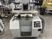
I acquired a Harig 612 automatic a while back at auction. It was outfitted with two axis DRO (Sony Magnescale) and specialized vacuum fixturing held down on a permanent mag chuck. This was a couple of years ago. I'm just now getting around to trying to get it operational, now that I've found a spot for it in the shop.

This machine was bought online, no chance to inspect, and I opened up the power cabinet today and saw a Dayton AC inverter (VFD?) mounted inside. I think this was a user retrofit, but I'd like to know if anyone has any observations about that. I don't see any mention of that in the (skimpy) manual. This machine was apparently used at some point in a healthcare hardware manufacturing setting (division of Siemens according to some notes with documentation).

I have not yet tried to ferret out what the VFD may be talking to, but I did apply power, and nothing happened, so there will be some sleuthing needed.
 
I have never seen a Harig with a factory VFD but mine have them added on.
In case of power fail some of mine need the VFD to get it's button pushed on the VFD to bring it back to life.
Depends on how the reset is wired and drive parameters set.
Bob
 
Very interesting. To ask a stoopid noob question, is the use of a VFD to allow for better control of various diameter grinding wheel speeds?
 
Very interesting. To ask a stoopid noob question, is the use of a VFD to allow for better control of various diameter grinding wheel speeds?
That is one use.
More for me is that I can change the hardness or cutting characteristics of a given wheel for a specific job.
Added plus is that you do not have to wait forever for the wheel to stop plus the soft start.
Bob
 
Very interesting. To ask a stoopid noob question, is the use of a VFD to allow for better control of various diameter grinding wheel speeds?

That's certainly possible. Another possibility is that the VFD let's the machine run on single phase power while still keeping the smooth three-phase balanced motor.
 
If the VFD is set to act as a brake, make sure it's not too aggressive. You don't want wheels spinning in the adapter.
No but if a need to stop for whatever reason a 20-30 second stop is so much better than a coast.
How many have "helped" a grinding wheel/spindle to stop as it seems to go on for a long time with a good spindle.
I've seen and I have done bad things because the darn thing just wants to spin forever.
VFD great here if nothing else used.
Bob
 
Diagnose the VFD non-starting first. "Dayton" didn't make that VFD. First step is to call or email Grainger parts and get them to email you a PDF of the manual and find out from them who actually manufactured it. Worst case you need to replace a VFD for a small 3 phase motor, not a huge dollar consideration.

Once you get the VFD back to life, if it still isn't working, there is often a method to reset it. On a TECO recently I found I just had to put a 1 into a certain parameter and that did it.

Lots of help online from guys with VFDs.

metalmagpie
 
I'm reviving this thread since it's about the same machine, and the same guy resuming the work on it...
Brief recap: Harig 612 automatic, doesn't yet power up from last round of putzing with it. In the maeantime, one of my guys (no longer here) had his kid helper (no longer here) do some disassembly and cleaning, and I think cleaned off some control panel labeling that was on the machine, and now I also cannot find any s/n ID plate on the machine in any obvious location.
Questions:
1. Does anyone know of, or have, a manual for this machine, and if so, does it contain wiring diagrams? I would REALLY like to have a manual. Willing to pay some reasonable fee for a copy.
2. Can all the control panel switches be identified from a photo of the machine?
3. Is there a supplier of Harig parts that would typically carry electrical panel-mount switches used on the machine, or will I need to do the cross-reference tango on that?
4. Is there some secret location where I might find a s/n?

Thanks for the help in advance --

IMG_0573smaller.jpgIMG_0574smaller.jpgIMG_0575smaller.jpg
 
Just a brief follow-up:
I did locate a manual, however it has no electrical detail schematics. It looked like there is a single page block diagram, with a lot of white space on the page. The switches are seemingly identified as to function in this manual, so I have something to work with at least.

If anyone knows where the s/n plate would have been on these machines, that would be a good fact to know. Maybe it is covered up somehow.
 
Not sure about the automatics, but on my manual Harig, the S/N is stamped into the casting at the very top of the column where the vertical lead-screw comes thru, facing up. You pretty much have to get on a ladder to read it.
 
Start with the leads that come out of the VFD labeled T1, T2, and T3. Trace the wires. Do they go to the spindle motor?

Assuming yes, now get out your voltmeter. Locate the lines on the VFD labeled L1 and L2. Power up the machine. Is there AC power at L1 / L2?
 
Thanks to everybody chiming in on this. As it turns out, it looks like things are working on a basic level. The VFD is connected such that the spindle-on pushbutton energizes the VFD. I was thinking that applying power to the machine as a whole would do that, but that has been proven WRONG. Any time I'm faced with a control system with a bunch of mag contactors and thermal overloads, I have to slow down a lot...

I was able to acquire electrical data from a guy who I later saw mentioned on this forum in another post, Jim Seyller(?), who was an employee at Harig building grinders until early 2000's, I think he said. Worked there for 40+ years, very knowledgeable, and has a service operation doing some consultation and field work. Volunteered a lot of basic info that was helpful, so I owe him. I recommend him highly as a source of Harig info.

The hydraulic pump appears not to be powering up yet, but I haven't chased down why. The lube pump for the ways works OK, haven't done anything yet with the Y-axis auto-step feature as far as check-out, but the twin DROs are working, and there is a device mounted on top of the spindle casing that also appears to be a 3rd-party add-on; it's a Schenck Electrodynamic Vibration Sensor, which I assume is an accelerometer that is read via the BNC connection at the back end. The VFD appears to be adjustable from the control panel, and I'm currently trying to find a drop-in replacement for the DC voltmeter that was shot, which I think shows the voltage value driving the VFD frequency via the pot mounted next to the voltmeter. Amazing how there are so many voltmeters out there, and none of them are the same dimensions as the one I took out...

The studs/T-nuts that were used for clamping the mag chuck to the table are completely corroded into place in the ends of the T-slots, and they may turn out to be the worst problem to solve on the machine. I haven't wanted to beat on them, but the PB Blaster has so far been ineffective.


Back
Top