What's new
What's new

Help Choosing a Manual OD Grinder

Halcohead

Stainless
Joined
Apr 10, 2005
Location
Bay Area, Ca
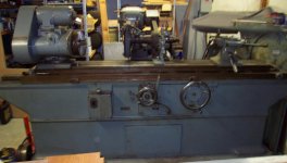
Looking for a manual cylindrical grinder for an upcoming prototype job. The job is described below, but I'm wondering if anyone can suggest grinders that are well suited for this (so far, all I've found are Myfords). I've never run an OD grinder (first article made by turning .0005" oversize, then lapping). Are there important or helpful features to look out for on OD grinders (eg. universal vs plain heads)? Buying used, are there any unusual things to lookout for compared to a standard lathe or surface grinder?

Job is:
Qty 2-30x shafts, 2" max diameter x 10" long, centers in both ends, with 3 different ground diameters, no tapers or ID features. Tightest tolerance is +/- 1um (+/-40 millionths) on a 3/8" diameter ground to a shoulder (with grinding relief).

Of course if anyone has a good candidate machine for sale, I'm now in the market!
 
Being only simple work, condition probably matters more than anything with that kinda tolerance. Do you need to grind the shoulders? My experience, that can be a lot harder than it seams it should be hence may pay to be a bit over generous machine size wise!

Whilst you can grind to those kinda tolerances, is that going to be good enough if the original was lapped? As presumably you probaly got a far better than ground surface finish off the lap if you did it right!
 
As a guy who bought an OD grinder without ever running one. Here are some thoughts for you. A decent OD grinder can Hold that tolerance, but its the operator that will make the difference in how many scrap pieces are made, and how long it takes to make a good one. Wheel choice is more Art than science, feeds are more important than speeds.

Is that small dia. near the end, or center of the shaft, you may need a follow rest, to keep things straight, and control chatter.

If only 30 pieces, may be cheaper to find a grinding shop to sub the work to, than buy a grinder and learn on a difficult project right out of the box.
Are these shafts rough machined, how hard are they.

If you are solid on doing this, practice on similar material and hardness. Holding Size and Finish at the same time, is the toughest hurdle.
 
Thanks for the quick and helpful replies y'all.

Shaft is stepped, thick in the middle and critical diameters are on the ends, so luckily no need for a steady rest.

I have an expert grind shop who considers +/- 1um loose, and they are doing these in production, however their lead times are too long for prototyping.

Operator will be me or an even more experienced machinist. This is in-house "toolroom" work where lead time is more critical than optimizing part cost. A "production" run would be 5-10 pieces, and the blanks for grinding are cheap so scrapping 20% isn't the end of the world.

The shoulders need to be ground for perpendicularity/runout reasons. Finish isn't super tight; these are seats for precision bearings. I only lapped the first article because I didn't have an OD grinder or trust my surface grinder setup.

Adam you're suggesting that a larger wheel will reduce the pain of grinding the shoulder? I should mention the shoulder is only 2mm high (radially), so stock removal should be minimal.
 
If concentricity and/or roundness is important you'll need "dead" centers in both tail stock and head stock.

If the shoulder needs to be dead square to a diameter you'll need a means to adjust the grinding wheel both left to right and up and down.

Gene
 
Job is:
Qty 2-30x shafts, 2" max diameter x 10" long, centers in both ends, with 3 different ground diameters, no tapers or ID features. Tightest tolerance is +/- 1um (+/-40 millionths) on a 3/8" diameter ground to a shoulder (with grinding relief).
Half a tenth, eeeuw. On a .375 diameter, on a 10" long part.

Ouch.

Other than that, Mrs Lincoln, I've run Landis, Cincinnati and Brown and Sharp and they all work fine. Michiganbuck can give you pointers on "this one has that, that one does this" so people do have preferences but if you can run a machine, they will all do the work. It's not magic, it's not an "art", it's standard metalworking but of course experience helps.

adama is right, wear is the biggest thing to watch out for because swarf is pretty hard on stuff. Usually the tailstocks go bad first, although that's not insurmountable, you just have to work harder to get the taper out.

For the job you describe, a plain grinder would be fine but if you think you might do short tapers or faces, then the universal is more versatile.

1R Landis would be nice. They come in both varieties.

About twenty years ago I got Mike Simard a new Chinee grinder - it used linear ways, hmm, but he made up some better way covers for those and was happy as a clam. Being new it held size very well. It was $15,000 but that was before Mr Trump helped our ailing grinder industry by putting on tariffs. Thirty years too late, maybe he can catch that horse :D
 
A few things to consider- you will want to lap your center holes to make sure your part comes out round, and its probably a good idea to make your life easier with a grinding gage like an Arnold or Federal. That way you can monitor your size within tenths while grinding rather than trusting a stop on the machine. Most machines, leaning on the table can bring a part to size without advancing the wheel head etc. Just stuff to consider.
 
(eg. universal vs plain heads)?

Make that work head - Plain is fixed, Universal swivels (think chuck up work piece, swivel work head and grind a point on it)

For a given size of grinder, Universal will always have less mass, less power and smaller wheels than a Plain

Traditionally, a Plain is strictly a between centers rig, while a Universal has a variety of spindle tooling and can either use the spindle LIVE or DEAD
 
This is awesome, thanks everyone!

The tight-tolerance diameters are all <1" long. Measurement is currently with a brand-new .1um (yes 5 millionth) 0-1" mitutoyo micrometer.

Dan, is there anything special about center lapping? Can I run one of these in a cordless drill with the work turning in a lathe? Center Laps | Grier Abrasive Co. Inc.

John, thanks for elaborating the distinction of the /workhead/, not the main grinding spindle. Yes it seems like a universal workhead would be quite a bit more useful for me.

If concentricity and/or roundness is important you'll need "dead" centers in both tail stock and head stock.

If the shoulder needs to be dead square to a diameter you'll need a means to adjust the grinding wheel both left to right and up and down.

Gene

Got it, thanks. For some reason I assumed the workhead center was always dead, but it sounds like that's not always the case. I would be surprised if a live centered workhead were precise enough for this job.

Is it common to be able to tram the main spindle axis parallel to table travel, or is this usually scraped in?
 
Is it common to be able to tram the main spindle axis parallel to table travel, or is this usually scraped in?

Table is usually two piece and the upper section swivels on a centered pin, and is clamped / unclamped as needed each end.

"getting out the taper" - always done - is thus enabled - not to mention that also any common taper - up to a reasonable point - is equally available

Fairly easy to see the stacked tables on my antique #4 (14 X 60) B&S Universal
 

Attachments

  • DCP_0938.jpg
    DCP_0938.jpg
    91.6 KB · Views: 132
A few things to consider- you will want to lap your center holes to make sure your part comes out round, and its probably a good idea to make your life easier with a grinding gage like an Arnold or Federal. That way you can monitor your size within tenths while grinding rather than trusting a stop on the machine. Most machines, leaning on the table can bring a part to size without advancing the wheel head etc. Just stuff to consider.

This. All three of these are paramount to your being capable of good, and repeatable work. And each are no less important than the others. Seriously.
 
This is awesome, thanks everyone!

The tight-tolerance diameters are all <1" long. Measurement is currently with a brand-new .1um (yes 5 millionth) 0-1" mitutoyo micrometer.

Have you played with measuring some gauge pins and seen what that really is measuring? Getting to 0.1 micron with a even a digital g clamp seams over optimistic IME. If this is truly for high precision bearing fits, hope you have some kinda cylindrical measurement capability too, That said, if your cylindrical and with out taper, you can at least know your shoulders will be square, 2mm land is not such a issue, when you said 3/8" diameter journals and 2" od, that would be a fair bit more contact area!
 
Can I run one of these in a cordless drill with the work turning in a lathe?
You can hold a tenth pretty easy, half a tenth hmmm, that's not going to be so easy but prepping parts with a cordless drill ? C'mon now ! Get serious !

I have had some experience with the Cen-T-Lap kinda machines (there are several) and it wasn't pleasant. Other people claim they work well. Maybe I'm just a dork. But for half a tenth, ouch, you may end up with the Jones & Lamson (or is it Jones and Shipman ? One of the Joneses, anyway) center grinder that has a real grinding wheel that it dresses and orbits around the center.

Not so sure about how good Arnold gages are at half-tenth control, either. They are mechanical and have moving parts. High production grinders had electronic gages with squeezy-type fingers.

If you can open that tolerance up to a tenth, this would be much easier. What kind of bearing are you using that needs such a tight tolerance on the bore ? Is this a real tolerance or one of them imaginary things that people like to throw around ?
 
...
Can I run one of these in a cordless drill with the work turning in a lathe? Center Laps | Grier Abrasive Co. Inc.

.....

Yes you can since you are just basically polishing the hole and removing burrs or heat treat distortion.
You can also put the lap in a drill press and put your part in a big vee block.
Now here is the oh-poop point. They wear fast so you need a way to redress the angle on the lap.
Center lapping machines have a built in diamond dresser so easy.
I guess you could chuck the lap in a lathe, put a diamond dressing bit in the holder and retrue the angle as needed.
These guys will not fix a bad hole without a ton of effort and it should just be a kiss.

In one place they had all kinds of problems with "lobey" centerholes from which the grinders would then make not so round parts.
I asked them to put a small (2 second) dwell in the centerdrill cycle before the retract on the rough stock.
The machinist making the centerholes never considered that you drill a helix and you then tell the machine get out as fast as possible you end up with that helix still in the area on the part the grinder needs.

I know you don't want to let sit or dwell a cutting tool. Rubbing is very bad. But you want that first hole good.
Done right the lap step is not even needed.
Bob
 
Thanks Bob that's super helpful. I've wondered about dwells on centerdrills in the past; it's nice to hear confirmation this can be a relevant detail for tight-tolerance work.

Have you played with measuring some gauge pins and seen what that really is measuring? Getting to 0.1 micron with a even a digital g clamp seams over optimistic IME. If this is truly for high precision bearing fits, hope you have some kinda cylindrical measurement capability too, That said, if your cylindrical and with out taper, you can at least know your shoulders will be square, 2mm land is not such a issue, when you said 3/8" diameter journals and 2" od, that would be a fair bit more contact area!

The 2" OD is the max diameter of the part, but no critical step is larger than 2mm radially.

The mic was checked against certified brand new gage blocks and deltronic pins. All repeated and matched within 10 millionths (~.2um). Also checked against a 5 millionths LVDT, which matched as well. The tolerance is +/- 1um, /not/ .1um, so the .1um resolution micrometer was chosen to have better than "10:1" resolution.

Circular runout checked with a lever type LVDT on bench centers. So far no issues.

Emanuel, these tolerances are standard for high-speed precision bearings, and can be found in any bearing handbook. They're neither "imaginary" and nor can they be changed.
 
Most of my experience is with 62Rc carburized parts, so keep that in mind. I would love to have a centerlap machine but I get by using carbide center laps (suppose more of a center reamer but. . . ) had good luck with them- both in a drill press and lathe with a center in the headstock. Someone makes coated abrasive center laps that you simply replace rather than dress the lap but I don't recall who makes them. You are not removing much material- just repairing the geometry. Most Arnold gages use a tenths dial indicator like a bore gage as the readout. Mine is an old worn out boat anchor, but gets the job done but then I'm happy with +/-.0002 on most stuff.

As far as taper- my jobs are repeats mostly so I have an old part that goes between centers, then I indicate that in with a tenths indicator, grind it and then tweak the table until its straight. I have an indicator on the swivel table so I can see how much i'm swiveling it with each adjustment. Just my way of doing it.

Dan
 
If you are going to do close jobs best to get a 1 and 2" dial micrometer.
Use dial micrometer as a comparator to proper Jo Block .. you don't read the numbers.
We used to let a close job sit on the cast iron plate for a half hour / some jobs for a hour to final measuer.

40 mills total is easy enough for a good grinder but measuring device is very important.
Must get room temperature or print stated to be sure..

*Johnoder mentioned grind the center in the head that is very important. and the tail best dead IMHO.

Abrasive center lap is OK but run it in a trammed mill or drill press or it will run a bit wide angle..
Often that does no harm but it is easy to tram your mill or drill press. for the drill press I have simply put a shim under my V block to make square to spindle.

A grinder hand used to the machine for spark-out and in-feed for perhaps 5 millionths is some times a one or two finger push on the wheel head or the work head...even on the part with a nylon stick..
So do make a few extra to play with.

QT Zahnrad: [ monitor your size within tenths while grinding rather than trusting a stop ]
for this idea make and try/test a size still in/above limit just to see you can make it safely.

Also for practice you might target a size, grind it to 50 millionths over that size + 6 millionths, then blue it up and see how much it tales to get a spark/take off the blue or get 6 mill take off.
Yes back in the day we used a grease pencil, not a ceramic marker.. the grease pencil was much better for close jobs.
 
Choosing a grinder find one with a tenths dial with large enough spaces to be able to see/stop at half tenth.
if going into grinding some machines have tarry right and tarry left..this allows a spark-out at a shoulder.
often id doing much shoulder work one might turn the wheel head so the shoulder is done with a dressed side noyt just the wheel's manufactured side.

Here is a Myford as you mentioned Myford MG12 OD Precision Cylindrical Grinder 5" x 12" - business/commercial - by owner - sale
I have no idea if this is what you want as I have never ran this machine.


Back
Top