What's new
What's new

Understanding what this controller does

SirRage

Aluminum
Joined
Sep 18, 2016
I'm wondering if there is a better place to post this but I'm starting here because this is a surface grinder wiring question.

The grinder was labeled 220 but the shop the grinder came out of was wired 480, and it would not run without a 480 transformer. This looks to be a dual voltage machine and should work in either 480 or 220 without replacing parts (I could be wrong about this), you just need to wire the mortors correctly.

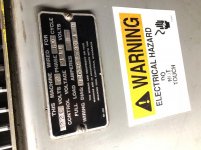
Inside the cabinet, I see a dual voltage step-down transformer (480 or 240 input to 240 or 120) and some kind of motor controller coil? The transformer is single phase so I think it's for the motor control. The wiring diagram shows the machine is a total of 2HP with the spindle, pump and hydrolics running.

IMG_0170.jpg
If I understand that chart, 3 phase 240 will be 3hp max, and 120 (if it got it's volts from the transformer) would be 2HP.

IMG_0191 2.jpg

I'll have a look at the motor wiring when I get the machine on Friday.
 
The wiring diagram that you posted has a table in the top left corner, which shows how input power which is 220, 440 or 550 volts gets connected. So it might be enough to simply connect your 240v power as indicated for the 220v. The difference is within the normal 10% design margin.

Or have you already tried this, and it doesn't work?
 
The first picture you posted just shows the max ratings for various voltages that the GE contactor ( just a 3 phase relay) can handle. The coil that operates the contactor is specific for a particular voltage and can be changed out. The machines control power voltage determines what contactor coil is used. The coil voltage is stamped in ink on the side of the coil, 110v in your pic. I’m on my phone and can’t read your print well enough to help with it
Keith
Edit- the transformer that you refer to is probably a control power transformer and steps the 3 phase line voltage down to 110v single phase control power

Sent from my iPhone using Tapatalk Pro
 
Main motor name plate picture would help if a better print pic can’t be had. The fact that the control power transformer has multiple taps for multiple supply voltages certainly implies that the motors can be wired for any of them


Sent from my iPhone using Tapatalk Pro
 
After studying it for a while now I think all I have to do is change the L3 going from the transformer from H3 to H2. The spindle motor does not have a wiring diagram on it, but indicates two different speeds for 230 and 440.

Going to set up the phase converter tomorrow and see how things go.
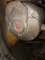
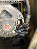
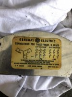
IMG_0221.jpg
IMG_0219.jpg
IMG_0222.jpg
IMG_0223.jpg

Sorry about the orientation of these photos. They looked fine on the computer, but not all image processors use the metadata for orientation.
 
After studying it for a while now I think all I have to do is change the L3 going from the transformer from H3 to H2.
Normally you would have to change the overload heaters on the contactor as well. That's the ones to right and left of the actual contacts. There's a chart somewhere which tells you what size heater for which load / voltage.
 
Get that there are two separate circuits here.
One is the single phase control circuit that runs your pushbuttons and "pulls in" the relays.
On picture one note that the coil is labeled 110. You jumper your control transformer to provide this.
You can push the center of the conatactor (with power off) to see what this magnet does.

The other circuit is motor power.
On both right and left are the heaters labeled 4.19A, these are like toaster wires connected inline with your motor and make enough heat when past their rating to pop the overload. The reset is that black lever/pushrod sticking out on the right side.
These are changed with input voltage and the motors are reconnected in their housings for the new voltage.
The safe amp draw at differing voltages should be on the motor nameplate.

There is not two speeds for the spindle motor. There are two wiring configurations for the different voltages.
This must be changed inside that plate where the wires come in.
For 440 lines are on 1,2 and 3 and 4 is connected to 7, 5 to 8 and 6 to 9.
For 220 Line1 together with 1 and 7, Line2 with 2 and 8, Line3 with 9 and 3 and 4,5,6 are connected together.
You will burn up the motor if you do not get this right inside the motor housing.

All of your 3 phase motors need this reconnection inside before you apply power.
If they rotate backwards flip any two lines, Usually you can just swap two of the main inputs to the machine.
Always test the spindle for direction with no wheel on the machine as backwards may unscrew the nut and be a bad thing.
Bob
 
Thanks Bob,

I'm used to seeing cables go to a junction box but in this case, the cables go straight into the motor. There looks to be two places where a plate can be removed on the spindle motor, one plate on the right and one on the left. The right plate makes mentions of bearings needing to be greased every 10 years and the left plate has the specs of the motor. Should I remove the right plate and see if the wires are there?

I just wanted to ask a few more questions before jumping in and taking more things apart.
 
Pull the plate above where the wire conduit comes in.
Here you will normally find the wire connections for differing voltages, this is pretty standard.
The motor wires should be labeled 1,2,3,4,5,6,7,8,9 and be attached to each other as above to the lines.
The exception being if a motor has been rewound to run on one voltage only but this is rare to come across.
Be careful pulling this wiring mess out where you can see it.
Sometimes the leads have writing on them, older stuff usually has a metal band with numbers, vinyl "tags" on wires can fall off and then you are lost although one can ohm them out if you understand windings.
Real old wires may also have brittle insulation which may crack when moved so you have to cover them with electrical tape or shrink tube when putting back together. Watch for this on any old machine and inspect each wire.
Bob
 
Thanks Bob!

I'll have a look at that tomorrow. The coolant pump has a diagram stamped on it's info plate, which is nice. If I don't see anything written down I'll use a meter and see if I can figure out if it's a delta or Y configured mortor and go from there. I'm still learning but I'm figuring it out.

Now I just need to get my hands on 15 gallons of Mobil 1405.
 
Making progress. Found the plate to remove for the spindle and there was a wiring diagram behind it. I'm wondering if I can shrink tubing ihstead of electrical tape but I have a feeling i need to find a cap or something else because the ends of the screws need to be covered instead of exposed.

I'm going to document how it's wired now before removing anything and test to make sure I don't mix up the phases with a meter.

IMG_0220 2.jpg
IMG_0235.jpg
IMG_0237.jpg
 
Electrical tape is the standard method used by about everyone for a very, very long time and is field proven.
You wrap in one direction extending past the end, fold it over and wrap back in the other direction.
This covers the end and is easy to remove and change and you don't have to cut it off.
You will see how it's done by unwrapping one slowly.
There must be a name for this but I have no idea what it is so I just call it "an electrician wrap" when teaching it to others.
This connection method means the wires must have ringlets and are screwed together.
I would not use shrink tube. Think that these connections will be under constant vibration against the housing which your hands will be connected to through the structure and you do not want to be the path to ground.

Your wiring plate is the standard WYE and contains more information than many do.
Note the "Y" shape in the first info on the plate plus the fact that delta has a different low voltage connection pattern.
Easy-peasy. Don't overthink it.
Going to half the voltage means twice the amps so heaters and fuses get doubled. This is important when going high to low or 1/2 size when going the opposite direction which is more common for me.

Phasing is no big deal if you do not have a phase indicator (which I have but never use), a quick pulse of power shows rotation direction and you just swap 2 leads.
I don't like hitting a hydraulic pump backwards as some are not happy with that so I'll manually hit the spindle contactor bar with someone watching the direction. (Yes you should never poke your finger or much better yet a wood stick inside a live panel...but.....)
Get that control transformer right first as your info seems weird or I am missing something.
Disconnect the output from it, apply power and check the voltage that is gonna hit your coils and pushbuttons.

All of this is so simple and like falling off a log once you have done it many times......but I do remember my intro and how confused and afraid I was so hope I've helped.
Be safe and respectful when probing or working in any panel. Isolate and cap off sections you are not sure of.
Bob
 
Found a PDF with heater info if someone comes across this thread looking for that.

http://www.cooperindustries.com/con...s/resources/pdfs/instruction-sheets/if698.pdf

So the 419A which was in the first photo are probably okay. Those are of my Brown & Shape No. 13 grinder - which might be 230 and not 480. At the time I thought the controller was the same so I used that photo because it was more clear. Now I know the heaters are different.


Back
Top