What's new
What's new

Another Doall 16-SFP rebuild attemp...already lots of questions

DanBrub

Aluminum
Joined
Feb 14, 2019
Location
Tennessee
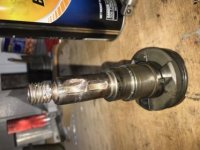
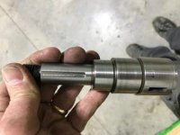
Hi folks, I’ve recently acquired a 1957 DoAll 16-SFP vertical bandsaw and have been reading and re-reading posts on this forum on rebuilds of old Doall saws. In my case the saw looked good from pics but as you might expect a pretty coat of paint can be deceiving. It ran but jerked and bucked like crazy so the investigation began. Top band wheel looked good and turned smooth. Bottom wheel was another matter! It had lots of slop so off it came. What I found was disappointing. Here is pic of the input shaft (after I removed it from tranny.

6CEFD394-57A8-41BB-AA2C-29E08E37632E.jpg

The woodruff key was gone but someone had hand drilled into the shaft and tried to thread for a set Screw!! Needless to say it was not successful! This brings me to my first question. I can tig weld the shaft to build it back up and turn it to size plus fix the thread and recut the key way but I don’t know the steel formulation so worry a bit about it getting to hard and I will have trouble cutting with HSS. Any advice?

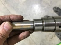
While we are on this shaft...the bronze bushing has about .015” clearance (shaft dia is 0.748”) so I’ll rebush this. Second question is why the slots are cut into this shaft and bushing? I don’t see any key that this slot engages so wondered why it is there! Here is pic
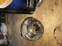
13D7F2FA-4720-4552-A9F2-0AE98EEC817D.jpg

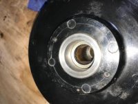
Ok on to the bandwheel. There was a steel bushing in the center of the Aluminum bandwheel. Is this original or was it a repair? It came out with some heat and light pressing and the bore of the Aluminum looks good so making another steel bushing should be easy. I hope if it was a repair that they did a good job getting it centered! Pic of wheel and bushing:

9552AD96-DDD1-450E-ADBA-905AB7DF9B80.jpg

Now some transmission issues/questions. The tranny came apart easily...in fact too easily. The bearings were not tight in the case to the point that if a bearing started to bind the bearing outer race would have spun. Anyone recommend the best way to correct this when I get around to putting it back together?

Next the variable speed pulleys (I think they are called Reeves!). They don’t look too bad but I’m not sure they were installed correctly and looking at the parts diagram I can’t determine. The pulley assembly on one end is flush while on the other end is counterbored. Which end faces the snap ring?

5D3582FF-DDCF-4D6F-A416-3385117FFCA1.jpg24B3E7F9-248D-48B2-A5ED-2B0BA80A4DE6.jpg

Many more questions soon

Thx Dan
 
Dont worry about your tranny,there is a lot of sense in slip fits in a part thats not heavily loaded.......namely people dont flog them apart with hammers......as to the keyway,if you weld up the old one ,the shaft will very likely bend more than somewhat.....depending on how bad the keyway is,it might be a solution to clean up the cut,and make up a custom key ...If you do weld,use plenty of preheat,and use a 310 type stainless....usually the rubber on the wheels is the biggest issue.
 
Thx John.k good to know the loose fit of the tranny bngs are not of too much concern. Mike at Doall tech support emailed me a blueprint of the shaft so worse case I can make another one. Not sure whether to use annealed 4340 or maybe 1144...what would you use?
 
Well, here is an update on the Doall 16 SFP. I tig welded the output shaft using silicon bronze hoping the reduced heat would minimize warping of the shaft. The original woodruff key pocket was pretty bad do it tigged it up too and cut a key way on the other side. Also replaced the brass bushing and cut the matching slots ( still not sure what purpose these serve)
Before: 5D5DF504-498F-43CF-9A90-20808E316DA8.jpg
After: 004AFAEE-9291-468C-91C2-3A6E218152ED.jpg
51611625-BDE6-4564-8028-11C1705562A6.jpg
B06E8EEB-050D-4517-A0F3-854D7565C587.jpg

Because I have to remake the bushing in the output band wheel that this shaft goes into I was able to clean up the diameter by turning it a few thousands less than it was before
 

Attachments

  • 487D9C7D-68A4-453B-B5DA-3781B115C6F5.jpg
    487D9C7D-68A4-453B-B5DA-3781B115C6F5.jpg
    19.8 KB · Views: 88
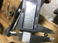
Next issue. The gear selector is a mess. Someone did some welding on it in the past but you can see the wear is so bad the ball bearing retaining hole on one arm is worn to the point the ball is loose. Both balls are not round anymore. I’ll probably build up some weld around the bad arm so it will hold the ball. I tore Ararat an old 6004 bearing and the ball is about .009 larger that what is in the arm now.
C3E83158-BCC0-476F-816A-D510308C214F.jpg
Old ball
3E2D17F2-D653-4D94-95D0-BF485FD4DAAA.jpg
Ball from 6004 bearing
B6A05D3C-67CA-4093-B623-80A3B64D55C0.jpg
 
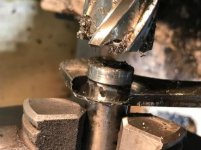
Worked a bit more on the saw today. I’m retired so have time to tinker. I’m a newbie at precision machining and my lack of experience showed up today. A previous owner had put a steel bushing in the driven band wheel and it was badly worn so I am having to replace it. I had machine the tranny output shaft slightly under size to true it up knowing I would be making the mentioned bushing and turned the bushing to fit this shaft. My rookie mistake was forgetting that to broach the key in this new bushing I needed a broach plug of the correct diameter!!! Oh well spent the next couple of hours making this broach plug! I’m sure most of you could have done this in a few minutes but I’m still parinoid cutting almost 1/2” deep slots with that little 3/16” endmill. Maybe someday I’ll push it till it breaks just to learn the limits
 
I have a pile of DoAll manuals, can send you one if interested. I'm also told DoAll has manuals online. Let me know if you interested, I'll check to see if I have one for your model.
 
Thx for the offer...a guy named Mike in DoAll tech support emailed me a digital copy of the parts manual for my model so I think I’m good. The digital copies are not great but good enough. I found a copy of a setup instructions for the saw that has helped as well.
 
Today’s effort: I was going to build up the gear selector with weld but decided to make a new one. Did save the shaft so at least didn’t have to make that. Used an annular cutter with center opening a little bigger that the shaft I wanted to save. Mounted the shaft in the lathe chuck so it was centered and the cutter in the tail stock chuck. Worked surprisingly well.
05FD0999-9CA7-4FDD-BD78-01663F4F1101.jpg
BCCAEFF0-A413-436D-89E9-6A6F342D4475.jpg

After roughing out the plate I used a boring head to cut the circle then drilled the holes for the ball bearings. Next I drilled and reamed the hole for the shaft. Turned the shaft to match and cut bevel for the weld. Then tig welded the shaft in place.
 
Hit enter too quickly! Guess I was excited about the next thing. The beast is alive! Got the transmission back together, mounted if back in the saw, hooked up the motor and to my surprise it worked...even shifted from high to low and the variable speed seemed to be working as I assume it should. I even got the air pump running...had to make a pulley for the motor to run it...I could have ordered one from McMaster but I needed to learn how to make a pulley cause I’ve never made one...thank goodness for YouTube to show me how!

Next I need to get the driven belt wheel bushing pressed into the wheel and install it on the output shaft. I measured the runout of the output shaft and it is about .004”. Not sure if that is ok or not!

Finally started disassembling the blade guides and the bearings that backup the blade. The bearing on top was frozen and it has a cover over the bearing that the blade rubs against. The cover was pretty worn. The bearing on the bottom guide was even worse. It is larger than the upper bearing and whatever was on the bearing to support the blade was completely gone. There was no cover on the bearing so I’m not sure what bearing number it is...will do some measurements tomorrow. A question for the forum is what the slotted threaded thing in the picture is for...and help.
E0E4585D-3A44-4F25-BDE9-49088038566D.jpg
 
Well disaster struck today! Here I thought I was past the troubles and had the saw to the point where it was almost ready for blade install. I had installed the band wheel and was checking the measured rpm against what was on the indicator. Everything was going great and measured rpm was about 10 more than what was shown on the saws indicator. I noticed a vibration started. Not too bad but annoying. As I was looking at the variable speed pulleys I noticed they were jumping around a bit. Walked over to the bench to get a flashlight and heard a loud bang then saw a large chunk of pulley fly out! End result? One of the variable speed pulleys broke
D1B49AB0-536F-43C6-8B9E-C19A9DB964BD.jpg
My heart sank as I know replacement pulleys must be changed as a set and cost far more than I paid for the entire saw!!!!
So much for trying to restore this saw close to original! I guess my only reasonable option is to go with a VFD to achieve speed variation. Not sure the 57 year old 1 HP motor will live up to VFD input even if I don’t overdrive it so digging through my stash for updated 3-phase motor.
 
I would have a go at brazing the pulley back together........it will require enough heat to have the whole pulley red hot,then a large torch on the crack.It should be relatively easy,however you will have to secure the two bits into position with a couple of socket head screws before heating.....use some CI scaling powder as well as flux.I once brazed the parts of a big dividing head back together after it smashed to bits on a concrete floor.
 
Hey John, I know the pics look like the pulleys are Cast Iron but unfortunately they are Bakelite. Guess I could try some industrial epoxy but I don't think even that would survive the environment.
 
If you could glue the parts back together and there was nothing to interfere with it maybe you could make a thin metal say 1/8” backing or re-enforcement disc and attach it to the back side of the shiv with some screws by tapping into the Bakelite .
You could also shrink and pin a thin walled steel ring or bushing around the hub to re-enforce that too if it didn’t interfere with anything .
A light cut on the running surface may be helpful to true it up if it didn’t affect the adjustment or belt tension too much.

Also I don’t know if they would be the same size or not but there was a model of variable speed drive Rockwell wood lathe from the 1970 s that used a similar pulley unit made from die cast aluminum .
I can’t remember the model number right now but there maybe something about it on Vintage Machinery .
Similar to this one I found in a quick search .
YouTube
Maybe you could find one of those that has been parted out .
I may have parts of one here that was taken out rather than repaired
If I do I’ll try and get some measurements on it but I can’t do anything on it for a few days .
Regards,
Jim
 
Much thanks to all the great suggestions on how to repair the Bakelite pulley. I'm afraid I've reached the point where I just ready to start using this thing to get some sawing done so I've convinced myself to go the VFD route. Found a new 3-phase 1-HP motor and I already have a 220V single phase input/ 220V 3-phase VFD so that is what I'm intending to use. I will have to build a platform for the new motor so the drive belt isn't so long so I'll post some pics as I go. Going this route means there are a pile of internal stuff I wont need...in fact it is going to look pretty bare inside the covers. If anyone needs some of the things I'm removing, let me know.

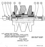
jmm03 asked me to post the parts breakdown of the pulley system so here it is:
pulley 1.jpgPulley2.JPG
 
Dan, you are probably wise going that route,I worked on a similar model DoAll with similar problems and I couldn't remember what the drive parts looked like. Looking at the drawing I think they were proprietary rather than Reeves, (and expensive from DoAll...)Toothed belt and tensioner with the VFD control may be the ticket. Please post pictures of your mod. Jim
 
Started converting the saw to VFD control. I decided to try and use the old belt instead of the suggested toothed belt with a tensioner. I know a toothed belt is more flexible but the driven pulley on the transmission is quite large so finding a comparable toothed pulley at reasonable cost might be a challenge. If this doesn’t work I’ll have to go the toothed belt route. To adapt the machine to the VFD I first found an inverter duty 3 phase, 1 HP motor. Next to give some adjustment I welded 2”x3”x3/16” angle together to obtain a 6” wide platform. I mounted this assembly at a 30deg angle thus for every 2” motion along the platform I get an 1” of vertical motion. That way I can adjust belt tension by sliding the motor along the diagonal. I milled slots for the screws holding the motor to the platform. So far everything seems to be ok and the system is quite rigid. Next I need to hook up the VFD and see what trouble I have created!!!
3D934B8F-93EE-4E1A-856D-422376A5C577.jpg DF3A5EC5-2729-4AED-A715-2A7860EE137C.jpg D445C09F-7269-432C-95D8-785C014D17AD.jpg C98B6374-59F8-4F1C-856F-8020CB5D6ACF.jpg
 
Started converting the saw to VFD control. I decided to try and use the old belt instead of the suggested toothed belt with a tensioner. I know a toothed belt is more flexible but the driven pulley on the transmission is quite large so finding a comparable toothed pulley at reasonable cost might be a challenge. If this doesn’t work I’ll have to go the toothed belt route. To adapt the machine to the VFD I first found an inverter duty 3 phase, 1 HP motor. Next to give some adjustment I welded 2”x3”x3/16” angle together to obtain a 6” wide platform. I mounted this assembly at a 30deg angle thus for every 2” motion along the platform I get an 1” of vertical motion. That way I can adjust belt tension by sliding the motor along the diagonal. I milled slots for the screws holding the motor to the platform. So far everything seems to be ok and the system is quite rigid. Next I need to hook up the VFD and see what trouble I have created!!!
View attachment 251565 View attachment 251566 View attachment 251567 View attachment 251568

I like your solution!

Doall mounted their VFD and DC motors on a riser, I think your solution makes it easier to adjust for different belt lengths......

Kevin


Back
Top