What's new
What's new

Anti-Backlash Mechanisms?

Brian Albin

Plastic
Joined
Mar 9, 2018
I would imagine many methods of eliminating the backlash in a Mill table's feed have been invented over the years. I am interested in machine design, and would like to read a book giving an overview and comparison of these various mechanisms and an assessment of the merits of each.

My Amazon book search for "Anti-Backlash Mechanisms" did not find any.
Does someone here know of such a book?
 
Thank you, Brian
 
 
Brian:

I can suggest that you get a good text on machine tool operation, possibly an older text such as was used in trade and technical schools. These texts will often have cross-sectional diagrams of different parts of machine tools. It will get you started and give you some understanding of the design of machine tools.

Unfortunately, I cannot put my finger on any particular text which will give you a description and design of anti-backlash mechanisms in feed nuts. I'll try to explain how these mechanisms work here. Basically, no set of screw threads and mating nuts is so perfect as to have "zero backlash". If this existed, chances are the screw and nut would be either very hard to turn or would "gall" ( a kind of cold welding process occurring when dry friction occurs between two metal surfaces). If the male and female threads are correctly cut so their profiles are identical or nearly so, full flank contact would occur between them. By making the screw out of steel and the nut out of bronze, two different metals with a hardness difference are used. This eliminates the chances of galling- which is most likely between similar metals.

In cutting the screw threads on the screw and nut, a very good contact between the flanks of the threads is obtained. However, some clearance between the male and female thread is a given. The trick is to minimize this clearance to reduce what is known as "backlash" or free play in the mating threads. I do not know of any great difference in designs for mechanisms to reduce backlash in feed nuts. All use a set of "split" feed nuts. These nuts are made in two segments, each fully threaded.
Each segment is threaded with the same starting point, and each segment usually has a keyway running the length of the body on the outside. The two segments are slid into the part of the machine tool which will hold the feed nut assembly. This holder is bored to a close fit with the segments of the feed nuts, and has a keyway running its full length. One end of this holder has a shoulder or other means to keep the feed nuts from sliding out. The entry end of the holder has no shoulder in order to slide the feed nut segments in.

Once the segments are in the holder, the feed screw is screwed into the first segment and it is then slid to a close distance from the second segment. The feed screw is then turned until it starts into the second segment. Some space between the ends of the two segments is critical. Typically, this is about 1/8".

One feed nut segment, the one butted against the shoulder in the bore of the holder, is said to be "fixed". The other segment, at the entry end is moveable. Some means of moving this segment and locking it in position is provided. This can be a shouldered screw engaging a groove turned in the outer diameter of the feed nut, or it can be more elaborate.

On some machine tools, the feed nut segments were designed with fine-pitch left and right hand threads on their outer diameters. These segments had spur gear teeth cut on their outer circumference beyond the threaded section. The holder had lefty-righty threads mating with the feed nuts. Each of these feed nuts was screwed into the holder and the adjuster mechanism included a shaft with two spur gear pinions to engage the spur gears on the feed nut segments. This spur gear shaft was brought to an accessable point on the machine tool and provided with a locking mechanism (clamp of some sort). This was probably the most elegant means of adjusting backlash and was used on some high end machine tools like bigger milling machines. Adjusting backlash was a simple matter of turning the adjuster shaft. This moved the feed nut segments in or out in relation to each other, to loosen or tighten up the clearance between the male and female threads.


Adjusting backlash is typically a simple operation assuming the feed screw has uniform wear over its length. The backlash adjuster is tightened until the feed nut lightly binds the feed screw. Then, it is backed off until the desired backlash is obtained. Bridgeport specifies a backlash of 0.003-0.005".

A lack of backlash is nice, but not a necessity. I've worked to better than a thousandth on machine tools which has plenty of backlash. The trick is taking it out by cranking back past where the milling table or lathe tool needs to be, then feeding in the direction needed so the backlash was taken out before travelling into the cut or going to a location with a milling table. I've gotten accurate work out on machine tools with half a turn of backlash, just worked around it.

On smaller feed screws, such as on lathe cross slides and compounds, backlash adjustments either can't be fit in, or are uneconomical. A backlash adjustment system needs some space in or on a machine tool. Backlash adjustment mechanisms are more often found on milling machines, jig borers, and machines where there is space for the mechanism.

However, with the "ball screw" if used in place of a regular threaded feed screw and nut, effectively is a "zero backlash" feed screw and nut. Backlash adjustment designs were largely something the machine tool builders came up with on their own. I can think of no specific text to suggest to you. Something like Shigely's "Handbook of Machine Design" has loads of design data, and I refer to it when I run calculations for things like gear design or shafting where a change in diameter and resulting stress concentration is an issue. Shigley will discuss "power transmission threads"- which is what a lead screw of feed screw is classified as. You can design the actual feed screw and nut to transmit a given load using the information in Shigely, but I do not think you'd find the nitty gritty of how an anti-backlash mechanism worked. Similarly, there were books of "mechanical mechanisms", but again, I do not recall seeing details of any anti-backlash mechanism.

My other thought is to get hold of some machine tool manuals with assembly drawings and maintenance instructions. SOmething like the manual for a Bridgeport Milling machine will give you an idea of how the backlash adjustment on the feed screws is designed, how it works, and how it is adjusted for use.

What it comes down to is that an anti-backlash mechanism is a means of moving a pair of segments of a feed nut relative to each other, axially (along the centerline) of the feed screw. A less effective means of taking up backlash on smaller feed screws sometimes consisted of cutting a slit or split longitudinally down one side of the feed nut. A clamping action at 90 degrees to this slit would tend to "close down" the feed nut on the feed screw. This could take up some small amount of backlash. A variant of this is used in micrometers, where the nut is often slit at 90 degrees, and the outside of the nut has a taper to it. This taper fits into a female taper in the frame of the micrometer and a means to force the nut deeper into that taper is made- usually threads on the outside of the nut and in the frame of the mike. By turning the nut relative to the frame, the "pinch" on the nut can be adjusted. This mechanism works for very precise and fine pitch threads and only gives a very small adjustment, likely in a couple of thousandths or less. Machine tool anti-backlash mechanisms are a lot bigger and rugged. I'm going to say if you get hold of a manual for something like a Cincinnati or Brown & Sharpe or K & T mill, you will find lots to study about the anti backlash mechanisms. Bridgeport is about the simplest, I think.
 
Thank you, Joe Michaels for that very informative reply!
It will take me awhile to digest it. I will reply once I have done so.
Thank you, Brian
 
I would imagine many methods of eliminating the backlash in a Mill table's feed have been invented over the years. I am interested in machine design, and would like to read a book giving an overview and comparison of these various mechanisms and an assessment of the merits of each.

Brian,
That would be an interesting book, please let us know if you find one.

You probably know this since you are investigating such devises, but I am pretty sure the main reason for anti-backlash mechanisms was to allow "climb milling" ("down milling", "down cut milling"). Climb milling has some advantages but it cannot be done on a machine without such a mechanism (or ball screws). No doubt someone can mention an exception, but normally on a manual machine it will mean "disaster".

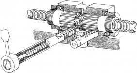
A few years back a PM poster sent me the attached photos of his backlash eliminator which neither of us managed to entirely figure out. From memory it was an automatic mechanism. I can't remember what machine it was (Cincinnati?) or who the poster was :(. No doubt there are other designs out there.

backlash 1950.jpg backlash.jpg
 
Hello Brian,

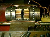
Here are a few pics of the backlash adjustment mechanism on my Cunliffe horizontal milling machine. It is very much like what Joe described above.

Bevel gears for X feeds....

IMG_0317 (800x600).jpg

Top half of bearing shell, with one nut and adjusting rings...

IMG_0320 (800x600).jpg

One half assembled...

IMG_0319 (800x600).jpg

Both halves installed and lead screw...

IMG_0321 (800x600).jpg

Once installed properly, you can still access the adjusting nuts by moving the x table far to the right, to further adjust the nuts as necessary...

IMG_0325 (800x600).jpg

Brian
 
The only antibacklash systems I know of that really come close to eliminating it are spring loaded. A good example is ball screws with two ball nuts with a heavy spring between them. The table or whatever is connected to one nut and the other hut just serves to take up slop in one direction. If the cutting load exceeds the spring pressure, there will be movement, but in most applications that would only occur in roughing. One of my friends paid a lot for ball screws for his Bridgeport and found that they only had single nuts and .002" backlash, not what he was led to expect. When he questioned the supplier (not Bridgeport) they said they added oversized balls to tighten the slack.

A common method for gears is similar, using two gears with one connected to the shaft and the other spring loaded. This is common in instruments such as radio tuning mechanisms and light duty servos.

Bill
 
I am grateful for the additional replies. Peter, Yes it was climb milling I had in mind. When I read that it produces a superior final cut, I wanted to try to get a mill made for it when I get one. If one mechanism was better at eliminating Back-Lash than the others, then I wanted to get that one; or if I become skilled enough, make and install such a mechanism. In your drawing, I thought perhaps the springs were doing all the anti-backlash duty.  Thank you, Sachmanram for the pictures. This is the first time I have seen the inside of one of these machines. Are those Dog Clutches inboard of the bevel gears?  Thank you, 9100 for the explanation about the spring loaded ball screws. The only anti-backlash device I had yet heard of for table feeds was the ball screw, but I had never been told how it worked. From what you have said, it sounds like the spring is actually the thing which removes the backlash, and I am guessing the only reason it is a ball screw instead of a standard thread is because the ball screw can take the spring pressure without galling. Is that correct? Peter, Yes If there is not such a book, someone ought to write it. Although it sounds like there may not be enough designs to make more than a pamphlet.
 
I am grateful for the additional replies.
 
Peter, Yes it was climb milling I had in mind. When I read that it produces a superior final cut, I wanted to try to get a mill made for it when I get one. If one mechanism was better at eliminating Back-Lash than the others, then I wanted to get that one; or if I become skilled enough, make and install such a mechanism.
In your drawing, I thought perhaps the springs were doing all the anti-backlash duty.
 
Thank you, Sachmanram for the pictures. This is the first time I have seen the inside of one of these machines.
Are those Dog Clutches inboard of the bevel gears?
 
Thank you, 9100 for the explanation about the spring loaded ball screws. The only anti-backlash device I had yet heard of for table feeds was the ball screw, but I had never been told how it worked. From what you have said, it sounds like the spring is actually the thing which removes the backlash, and I am guessing the only reason it is a ball screw instead of a standard thread is because the ball screw can take the spring pressure without galling. Is that correct?

Joe Michaels said: "I do not know of any great difference in designs for mechanisms to reduce backlash in feed nuts."
This is the very last thing I expected to read. I once saw a review of a book detailing fifty different designs of cavalry saddle submitted to the US Army over a 75 year period. That was for nothing more than a chair to sit on the back of a horse!
Since backlash is an actual problem, I thought there must have been hundreds of clever inventors during the last two centuries scheming up ways to rid us of the scourge.
 
Peter, Yes if no one has written this book then someone ought to. But it sounds like it might only make a pamphlet.
 
I am grateful for the additional replies.
 
Peter, Yes it was climb milling I had in mind. When I read that it produces a superior final cut, I wanted to try to get a mill made for it when I get one. If one mechanism was better at eliminating Back-Lash than the others, then I wanted to get that one; or if I become skilled enough, make and install such a mechanism.
In your drawing, I thought perhaps the springs were doing all the anti-backlash duty.
 
Thank you, Sachmanram for the pictures. This is the first time I have seen the inside of one of these machines.
Are those Dog Clutches inboard of the bevel gears?
 
Thank you, 9100 for the explanation about the spring loaded ball screws. The only anti-backlash device I had yet heard of for table feeds was the ball screw, but I had never been told how it worked. From what you have said, it sounds like the spring is actually the thing which removes the backlash, and I am guessing the only reason it is a ball screw instead of a standard thread is because the ball screw can take the spring pressure without galling. Is that correct?
 
Joe Michaels said: "I do not know of any great difference in designs for mechanisms to reduce backlash in feed nuts."
This is the very last thing I expected to read. I once saw a review of a book detailing fifty different designs of cavalry saddle submitted to the US Army over a 75 year period. That was for nothing more than a chair to sit on the back of a horse!
Since backlash is an actual problem, I thought there must have been hundreds of clever inventors during the last two centuries scheming up ways to rid us of the scourge.
 
Peter, Yes if no one has written this book then someone ought to. But it sounds like it might only make a pamphlet if there are so few solutions as it appears.
 
I twice tried to post that last one with your names Bold Faced, and it would not post. When I got rid of the bold, all went well.
 
Reinventing the wheel are we??

Single nut preload.jpg

This is from the Hiwin ballscrew manual. Page 20. In the manual, they stress being aware of increased heat build up and the inherent problems that can develop, along with some suggestions on how to deal with it etc.

As for ACME threads, well, the previous posts and suggestions pretty much cover it all.

More.

Double nut preload.jpg
 
Brian:

What I meant is the underlying principal whereby backlash is minimized (never quite eliminated) is the same, regardless of how simple or complex the mechanism surrounding the feed nuts happens to be.

The humble Bridgeport mill and its numerous clones all used about the simplest means of adjusting the feed screw nuts to minimize backlash. The more elegant or complex versions, as postings by Peter S and Sachmanram show, still come down to some means of adjusting the end gap between a pair of feed nuts having the same starting point to the thread cut in them.

As you note about saddles, there are countless variations. So it is with machine tool design. However, the underlying principals and purpose for which either a saddle or a backlash adjustment is designed remain as "common denominators". When I worked in Paraguay in 1918, the people rode horses to get around and to work cattle. A saddle was a rarity. Instead, the Paraguayans would put a regular bridle and a doubled=up sheepskin pelt with a girth on the horse, and ride. It did the job that in the USA, we'd have used a western style saddle for. Same purpose, same basis for design- to put a rider on a horse's back, spread the load out on the horse's back and make things halfway comfortable for the rider and perhaps go some ways to keeping him on the horse's back when riding hard or cutting cattle from a herd or rounding up strays. I've seen men using western saddles do just that, and I have seen Paraguayans do the same on their sheepskin pelts.

Getting back to backlash (sorry about the unintended pun), backlash, no matter how elaborate the means of adjusting the feed screw nuts, is never entirely eliminated. If it were, the feed screw would be clamped hard or bound in the feed nuts. Some slight amount of backlash is a necessary thing in order for conventional feed screws and feed nuts to work properly. The trick is to reduce backlash to some acceptably small value so climb milling can be done.

Discussion of the Asian imported mill/drills and clones of Bridgeports is a forbidden topic here. That being said, if we use the Bridgeport as the lighter and simpler end of the scale, you will find it has backlash adjustments on the X & Y axis feed nuts. Same system for both sets of feed nuts. As you move to heavier milling machines, I am sure the means of adjusting backlash in the feed nuts is correspondingly heavier and more elaborate.

In PeterS's post, we see a very advanced system, using ball-thrust bearings along with milled gear teeth on the feed nut sections. Gear racks move the feed nut sections from outside the saddle of the machine to adjust backlash.

In Sachmanram's post, we see a system not too far removed from the Bridgeport design, since the feed nut segments are keyed. If I am not mistaken, the X axis feed is accomplished by the two bevel gears toward the right, driving the X-axis feed screw with shaft keys. The X axis feed screw has a keyway running its length for the power feed drive. The gearing for the X axis power feed is placed to the right of the two feed nut segments. The two feed nut segments are in the red housing, and there are adjusting nuts on the left side for taking up the backlash.

The basis for most patents is the ability of the inventor to prove the uniqueness of their idea. Something like a chair could be argued as having nothing unique, yet I am sure there are numerous patents issued for chairs. It is not the underlying or basic principal which is patentable, but how that principal gets accomplished. A chair may have three legs, a one-piece pedestal, five legs, or any number of other methods of supporting the seat and back. Backlash adjustment mechanisms were made according to the design philopsophies of the machine tool builders and their designers, and this drew upon the class of machine tool- light, medium, or heavy duty, along with the size of the machine tool and its parts, and the intended use (production, heavy hogging work, toolroom...).

Getting the backlash adjusted to a minimum is the difference between night and day in how a milling machine behaves. get a milling machine where the feed nuts are worn knife-edged and try milling operations with it. Little or no backlash adjustment left and next to no contact left on the thread flanks between what was left of the feed nuts and the feed screw. One wrong move and the milling cutter will grab and pull in the work or bust the cutter or both. I've had the experience of being stuck working on machines that were in that condition, and it was a bit more challenging. Get a new set of feed nuts installed (assuming the screw is not worn unevenly over its length) and adjust them to minimize backlash and it's like getting a new machine after the hungry monster that mill had been previously.


Peter.......In your drawing, I thought perhaps the springs were doing all the anti-backlash duty.

Brian,
I don't think there are any springs in the drawing of the backlash eliminator I posted. I doubt any milling machine backlash eliminator relies on springs.

I think there are two different mechanisms being discussed in this thread - (1) backlash adjusters as found on a Bridgeport etc and (2) backlash eliminators as found on machines intended for climb milling.

BTW, I would not bother looking for an old manual machine with a backlash eliminator in the hope of improving your surface finish. I think it was more intended for being able to mill in both directions and possibly for improved cutter life. Not intended for regular jobbing work and a disaster waiting to happen most of the time.

CNC milling? That's a different story.

Happy to be corrected on any of the above!
 
Most anti backlash devices I've come across don't really solve the old conundrum of disproportionate wear on the lead screw. Most machines get the most wear on the lead screw around the centre of table travel. If you get the nuts set nice and backlash free in the middle of the table travel chances are the screw will bind up as you approach the end of the travel. I wish I had a £1 for every time I've been called to a " stuck table " that was just a backlash eliminator that became over tight.

Spring loaded or hydraulic devices try to solve this problem but I can't say I've seen one that I'd like to recommend under maximum cutting conditions. If you've ever seen a job get dragged under a climb milling slab cutter you'll know the forces involved.

Regards Tyrone.
 
Brian,
I don't think there are any springs in the drawing of the backlash eliminator I posted. I doubt any milling machine backlash eliminator relies on springs.

I think there are two different mechanisms being discussed in this thread - (1) backlash adjusters as found on a Bridgeport etc and (2) backlash eliminators as found on machines intended for climb milling.

BTW, I would not bother looking for an old manual machine with a backlash eliminator in the hope of improving your surface finish. I think it was more intended for being able to mill in both directions and possibly for improved cutter life. Not intended for regular jobbing work and a disaster waiting to happen most of the time.

CNC milling? That's a different story.

Happy to be corrected on any of the above!

I can't recall the make now but it may have been an " Archdale " but I can distinctly recall a machine I worked on in the past the had a spring loaded backlash eliminator. It was a bloody big coil spring that you could tension with adjusting nuts.
I'm pretty sure I have seen other makes with the same idea.

Regards Tyrone.
 
I am grateful for the additional replies.
 
Thank you, 9100 for the explanation about the spring loaded ball screws. The only anti-backlash device I had yet heard of for table feeds was the ball screw, but I had never been told how it worked. From what you have said, it sounds like the spring is actually the thing which removes the backlash, and I am guessing the only reason it is a ball screw instead of a standard thread is because the ball screw can take the spring pressure without galling. Is that correct?
 

That's about the size of it. The preload must be as high as the maximum cutting load so the screw is operating at max load all the time.

The Cincinnati cylindrical grinders have a hydraulic cylinder keeping constant pressure on the cross feed screw. Of course, there the holding the backlash down is only important on the finish pass which typically is a fraction of a thousandth and forces are low. You could add something similar and only pressurize it for finish cuts.

I make climb finish cuts on Bridgeport class machines frequently, only a thousandth or two, with forces lower than the friction level of the table.

Bill
 
As Joe, 9100, and others suggested, most any mechanical anti-backlash system is going to rely upon some way of forcing intimate metal to metal contact, with just a thin lubrication layer to keep things from freezing up. One enemy of these is friction and wear. Another is that the forcing element (springs etc.) isn't strong enough for things like climb milling; at least in both directions.

Could be you would want to consider "active" systems which (like active suspensions, active noise cancelling, etc. etc.) position machine elements with error correction in reference to some standard?

You might also check Amazon, Bookfinder, etc. for books on mechanical mechanisms. Lots of sources out there, ranging from a five volume (if memory serves) set to dozens of more modern sources.
 
From your initial post, I imagine you are delving into the design of anti-backlash mechanisms as a design exercise or research project rather than to build a working machine tool. I could be wrong and it would not be the first time.

A type of spring which could be "stacked" concentric with the feed nuts is the "Belleville Washer". These are truncated cones of spring tempered steel. They can be used singly or stacked as needed. An interesting application of the Belleville Washer is found in what is known as a "Limitorque" operator. This is a motor with reduction gearing and limit switches used to open and close large valves, sluice gates, and similar application. As the name says, the distinguishing feature of this device is the ability to "Limit Torque", hence the name. A Limitorque operator utilizes helical gears for the primary and intermediate speed reduction from the drive motor. Final drive to the stem nut or shaft of whatever is being actuated is by a hardened steel worm and bronze worm gear. The primary means of controlling a Limitorque operator are position limit switches. The final protection is the torque limiting feature. This is accomplished by taking the end thrust of the worm on the final drive with a "pack" of Belleville washers. If the gate or valve should "hard seat" on some debris in the flow passage or experience a mechanical bind, the torque applied to the worm gear increases correspondingly, and the end thrust developed by the worm increases as a result. When the end thrust overcomes the setting on the Belleville Washers, the worm screws itself out of engagement and trips a final electrical limit switch, taking out the motor.

The interesting part of this is the fact the Belleville Washer packs can be ordered in precise end thrust (which Limitorque correlates into output torque ranges). A further fine-tuning of the maximum torque is had by an adjusting screw to set the deflection on the Belleville Washers. I've been quite impressed by the ingenious mechanism and the use of something so simple but "elegant" (as engineers like to say).

Belleville Washers, set concentric with the feed screw, and having a threaded adjusting collar, could be used to adjust backlash and add some "preload" on the feed nuts. However, there is a trade-off. Pre-load produces friction and tends to squeeze out the lubricant from the feed nut/feed screw thread flanks.

On the Limitorque Operators, I've seen a lot over the years. We had six of them on some floodgates on a dam. These had stems with Acme threads cut in 3 1/2" diameter 300-series stainless steel. Think of a lead screw about 15 feet long. What used to happen with some reqularity was a stripping out of the stem nuts. Imagine a chunk of aluminum bronze about 6 inches in diameter x maybe 12 inches long with a 3 1/2" internal Acme thread and drive splines milled on the outside. We were caught between a rock and a hard place: if we lubricated the stem threads with grease capable of resisting the high pressures, the grease, when immersed down into the river water, was a perfect trap for waterborne grit and small debris. This stuff made it up into the stem nuts and in a matter of 6 to 12 operating cycles, we had knife edged threads in the stem nut. If we did not lubricate the stem threads with grease, but sprayed them with a hose to clean off the river-borne grit and debris and then applied a thin lubricant manually, the stem nuts lasted a bit longer. Another side-effect of using heavy bodied grease on the stem threads in winter weather (out on the dam, no enclosure or heat) was increased drag. During high water/flood stage conditions when the hydraulic loads on those gates was at its maximum, we actually wore out some of the bronze worm gears ahead of the stem nuts.

We also learned that the torque limit setting could be very finely adjusted to almost a "razor edge" thanks to those Belleville Washers. As I said, I've seen some hellacious damage due to a lack of lubrication on what are known as "power transmission threads". A feed screw in a milling machine is a smaller version of this. On the flood gates, when the gates were opening or closing, there is a range when the gate has a relatively small opening in which what is known as "hydraulic downpull" occurs due to throttling thru the gate and discharging water freely into the open on the downstream side. In addition to this "downpull", which puts the maximum load on the stem and nut, there is some "chatter" of the gate leaf (think of about 15 tons of cast iron, edges faces with bronze, able to be raised and lowered in guides under the water). The chatter of the gates would be so bad it would literally pound the bronze seating surfaces, cold working them until they split. Add the hydraulic force from the head of the water pushing the gate into its seat with resulting friction drag. The forces and things that happen to a sluice gate and its stem and operator were quite a set of lessons for me.

I can appreciate your wanting to design a "perfect" feed screw and nut for milling machine tables. However, going back to your analogy of the saddle, there are as many ways (and maybe more) of designing this anti-backlash mechanism as there are (or were) machine tool builders. All were designed to accomplish the same thing. I do not think any design ever resulted in the ideal of "zero backlash". We learned to live with what we had on those flood gates, and kept Cardish Machine Works busy from time to time making more stem nuts. I would have to say that once the ball screw system was perfected and came into common use, the quest for the better anti backlash design quietly faded away, not to mention the numerous builders of manual milling machines who similarly and sadly also faded into oblivion.

You simply can't have "zero backlash" with a conventional screw and nut. There HAS to be some slight clearance to avoid clamping the screw onto the nut, and to allow a film of lubrication. Once that is established, backlash, however slight, is a given. The trick is keeping backlash in workable limits to allow climb milling. As I said, I've used older and worn mills with a half turn of backlash in the X axis feed screw due to worn nuts. Despite that, I worked to the thousandth with no problem. If you work on machine tools, you learn to "take up the backlash" as a routine thing. If you work on worn older machine tools, you also learn how to deal with "stick slip" friction in the sliding surfaces when needing to take a fine finishing cut or make a very small adjustment to table position. A nice tight machine tool is sheer pleasure and a joy to work on, no question about it. But, in the real world, we had to work on what we had, where getting a job done was the main thing, not repairing someone else's worn out machine tools with materials and parts we did not have.

As I wrote, the idea of using Belleville Washers in a "pack" concentric with the feed screw to provide a very precisely controlled "preload" to the feed nuts is something I'd explore if I were designing and anti backlash mechanism. It is "simple but elegant".
 
Joe Michaels said: "What I meant is the underlying principal whereby backlash is minimized (never quite eliminated) is the same, regardless of how simple or complex the mechanism surrounding the feed nuts happens to be."
 
I see. Thank you, Joe. Perhaps there are enough designs to make a book after all. I think I would find it interesting reading.
 
Joe said: "I imagine you are delving into the design of anti-backlash mechanisms as a design exercise or research project rather than to build a working machine tool."
 
Joe, I am not building. It is only that I got to thinking about how little I know of how backlash is eliminated (or reduced) and I thought I would read up on it and was surprised to discover I could not find a book telling about the various designs. So I thought I would ask here if anybody knew of such a book.
 
Joe said: "I can appreciate your wanting to design a "perfect" feed screw and nut for milling machine tables."
 
I was not thinking of designing anything new. I figured good enough already existed, I only wanted to learn what the best existing designs are. And possibly upgrade to one of them if I some day buy a machine with what seems to be a lesser design. Provided I could fit the better design into the available housing.


Back
Top