What's new
What's new

Atlas #4 arbor press help

DeSelle

Cast Iron
Joined
Oct 23, 2006
Location
Midlothian, TX
Hi all,

This is a bit of a long shot but does anyone have an exploded view of the ratchet mechanism on one of these presses? I have one that is on the long list of items to restore but in the meantime I need to use it. I think there is a piece missing from the ratchet because it doesn’t ratchet. The arm just rocks back and forth.

Thanks,

Nathan
 
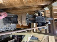
43D80B5A-9914-4587-B658-E306D64598EC.jpg55EA4360-3080-484A-AEE3-CDAFF579FE77.jpgThanks Rob,

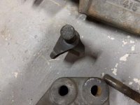
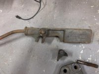
Here are some pictures of what I have. I am still trying to get it apart so I don’t have pictures of the insides yet. I looks like you might have to switch a peg or something but I’m not sure if the peg is missing or just in the wrong hole.
 

Attachments

  • 6440C2ED-8B3D-4297-B241-686E9E827BBD.jpg
    6440C2ED-8B3D-4297-B241-686E9E827BBD.jpg
    20.4 KB · Views: 134
  • FF7508A2-529C-4134-8F99-80FB66A93538.jpg
    FF7508A2-529C-4134-8F99-80FB66A93538.jpg
    19 KB · Views: 117
First of all, that's a nice press! You will have to visit a lot of shops before you find an arbor press bigger than that :D

I have a Dake #4 which is a near genetic copy other than they switched out some letters in the sand mold before pouring the iron....

It sits in my junkpile....err.......I mean....Storage Area :cool: awaiting me to get everything into the new shop space.


Bottom line is I think you are missing a pin. One of the 4 holes seems to be open in your pics.

The top pin slides, axially, to one of two postions, either all the way thru the cast "loops" on the top of the column in compound mode, or pulled back to clear the loops and just engage + hold the counterweighted arm with the handle.

In other words, in ratchet-mode the counterweighted arm/handle asm is pinned to the quadrant. You will get 3 or 4 or 5 or more "cogs" on each ratchet-stroke of the handle depending on how far you pull the arm.

In compound mode, the counterweighted arm/handle rotates relative to the quadrant. You will only get 1 "cog" on each very long stroke of the handle.

I think you are missing the pin which is painted yellow in my photo. I forget its something nominal like 7/8 or 1" diameter. Either 1018 or W1 drill rod, soft-state, would be my choice for another one, but literally anything steely be used,
 
Yes Matt is right that you look to be missing a pin, probably both pins. There are two pins that slide side to side to engage the handle, one is standard leverage and the other is high leverage. Matt's picture has the pin shown with a yellow head, where yours has an empty hole. These pins are very hard, not soft mild steel. Also you can not have both pins engaged at the same time, the handle will not move.
One pin slides in the hole in the side handle and engages a slot in the handle, his is the yellow headded on in the picture. The other pin slides in the holes on top of the main frame, when you push either pin in it should push the other pin out, so only one is engaged in the handle slot at a time.
That will let you know what length to make the pins and drill for a roll pin to not let it go to far in.
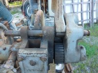
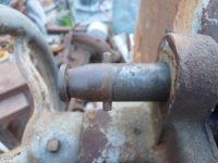
P1070543.jpgP1070544.jpgP1070545.jpg
Here are pics of my famco. first two pics are of each pin engaged and last is a closeup of the end detail. The pics show when either pin is in against its stop pin the end of pin is fully in the slot casting, but not past it.The handle with the slot floats side to side about 1/4" on mine, that is why from one side the pin looks short.

Edit: The pins need to be hard because the cast iron slot in the handle slides on them while under considerable load from the handle.
 
Last edited:
Thanks guys, this helps immensely. One more question, I am attempting to remove the ratchet mechanism to clean and inspect the insides. Are there are springs inside to worry about? I hope to get it apart tonight.

Thanks,
 
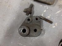
F62C5A22-180A-4CB6-A6C6-AA1FBAD70BA4.jpgB327063A-22CA-45C7-940F-1491D763949D.jpgDA6B3D0D-96B3-4D0D-930D-F6C25DEBC1C4.jpg5A77285D-92C7-4565-9B67-3C9011E83338.jpgWell in order to take it apart I had to drive that top moveable pin back. The back half of that was there but I didn’t see it originally. When I did that the ratchet pawl fell down and looked like it could work. I tried it once and it advanced the ram but would not snap back as I ran the handle back for another bite. It really seems like there should be a spring of some sort. Here are the pictures of what I found. Does it look like anything is missing?
 
Mine can get gummed up with dust and crud and ratchet not fall freely. I need to keep it clean and oiled so it works smoothly. Do you have both sliding pins as I showed in the pics I posted earlier in post #6?
 
Thanks guys. You’ve been a huge help. I’ll clean it all up and oil it so I can press these line shaft pulleys off. I dragged this press home because it was free and looked cool but also so I could use it to fix my other machines. Glad it looks like it will be useable
 
Unfortunately no, the inner most sliding pin was just a cut off bolt. I’ll machine a pair and try to figure out the correct lengths. Unless you can tell me? I need to get this thing down on the ground. Right now it’s up on blocks with casters it’s really hard to roll on pipes because it has some cast feet that won’t let it roll well. Hein* up its hard to use and work on
 
Length of pins is easy to figure out, look at my pics if needed, I did 2 pics, one with each pin all the way in, against its stop and you see where it goes to at the end. The one on the frame is almost twice as long as the one on the moving handle.
 
I did some investigation and think I gave you some bad info from my faulty grey matter earlier.

The pin that I have which performs the ratcheting function...6" OAL x 1" dia. It slides into the quadrant from the RIGHT.


The pin that slides from the LEFT, in order to engage both loops, should be 10" OAL in my opinion. This is the one that engages the compound mode. The 6" pin above would be pulled out and the hole in the quadrant would be empty.


Of those 10", it takes 2" of axial travel to engage the counterweighted press arm. So I looked at two areas,

The space between the loops is 2-1/2" so that would allow a little pin to be screwed into the arm from the side as a small handle. 1/4" dia would just work.


And at 2" of retraction I looked to make sure it wouldn't clip your hands as you turn the handwheel. Looks good to me.


Couple of other issues. Someone mentioned the pins have to be uber-hard...I don't think it matters, both Right and Left pins are just cantilevered when they are under load, so its just a problem of bending stiffness where hardness does not help a bit.

Its also possible that my idea to screw in a little 1/4" handle into the center of the 2-1/2" wide pocket will weaken it because it takes some away from the cross-section. I can't say whether Dake does it that way, you could probably get an idea if you studied the online manual's exploded view illustration.

Last, get that thing off casters !!! The ~1200# on wheels is waiting to send you to the ER or worse. Imo if you need to make the press portable, build a pallet base out of common 2x4s and get yourself a pallet jack. Then you can roll it all over when needed and it will still sit solidly without fear. See also: GRK-RSS structural screws for building strong wood structures.
 
Thanks Matt,

I picked up a couple pieces of 1” shafting that slips right in smoothly so I’ll make the pins from these. I had no plan to kept the press on casters I just had it on this rolling skid to get it out of the way while I sorted the rest of the shop out. I’ll drag it back out of its corner and get it back on the ground
 
Someone mentioned the pins have to be uber-hard...I don't think it matters, both Right and Left pins are just cantilevered when they are under load, so its just a problem of bending stiffness where hardness does not help a bit.

Nobody mentioned anything beyond hard, meaning not mild steel, Uber? Here is what I said:

Edit: The pins need to be hard because the cast iron slot in the handle slides on them while under considerable load from the handle.

You are partially correct that the pin on the right is only subjected to bending forces and hardness or lack of, probably is not an issue with that pin. The pin on the left is another story, it is also subjected to rubbing from the compound pawl, the rubbing force is as much force as you pull the handle. Mine is 12 tons and I use it to its max regularly for bending and straightening. The pin is as smooth and scratch free as the day I got it, it was unused. The slot in the pawl itself is showing signs of wear.
The pin that slides from the LEFT, in order to engage both loops, should be 10" OAL in my opinion. This is the one that engages the compound mode. The 6" pin above would be pulled out and the hole in the quadrant would be empty.
10" looks right from your pics.
I do not remove either pin when "changing gears" I often start something in high gear and shift to low gear when needed, keep the pins oiled and just slide them side to side. The one will push the other out of the way, no need to even remove your hand from the handle, it does need to all the way up though.
I would quickly loose the pins if they were not in the holes they belong in.
I picked up a couple pieces of 1” shafting that slips right in smoothly so I’ll make the pins from these.
This should be fine, keep an eye on the frame mounted, left pin for signs of wear if you do heavy work with it. Lube is your friend here also.
 
Another way I think about it...what do I want to wear out, a 2 dollar CRS pin or a casting that would probably be 4 figures from Dake...

In any case, these things will last a few more generations. Probably double digits if oil is used :cool:
 
Another way I think about it...what do I want to wear out, a 2 dollar CRS pin or a casting that would probably be 4 figures from Dake...

In any case, these things will last a few more generations. Probably double digits if oil is used :cool:

Could look at it that way, but unless you turn the pins diameter smaller at the working end it wont slide nice in the holes when it gets scratched up.

This conversation has lead me to the conclusion that I will need to take mine apart to inspect and clean it. There is a small chance what I felt was dried and hardened lube mixed with dust that, over the years was pushed aside to build up a ridge, feeling like wear on the metal.


Back
Top