What's new
What's new

Barnes 4 1/2 general questions

MoriMillMan

Aluminum
Joined
Jan 6, 2019
Hello everyone, this is my first post. I recently saved 2 Barnes 4 1/2 lathes from my father. (He bought them because the legs were pretty) I am new to lathes, but I’ve read “How to Run a Lathe” and have taken apart cleaned and put back to togeather most of a Barnes. Anyways... first question I wonder what the max spindle speed for this lathe should be? I’d hate to push it harder than it was originally intended to be. And second question I just finished putting the lead screws and carriage on the bed. When I tried to adjust the gib for the x axis there was no way to travel the full bed length without having BAD slop in the carriage. Is there something I can do to alleviate this? Or should I clean up the other bed and see if it works better? Or maybe the other carriage? I think I actually have carriage from one lathe and bed from the other cleaned up and put togeather now maybe putting them with the original would help? I was just trying to pick the best looking parts off each to make the best machine I can out of the pile. I think the only reason I chose the current bed was because the other had a broken bolt. Is it a bad idea to mismatch parts?

The purpose for this lathe (if I can get it operational) is just for me to learn the basics of operation have it to play with.

I should note that it is missing the original treadle and I will be looking for a suitable electric motor. If anyone has suggestions pertaining that I would appreciate it as well.

Thanks in advance for any input

-Dalton
 
Welcome to "barnsitus." Its a disease variant of the "old iron" type and commonly afflicts males of the "technically qualified" types.

Mismatch of parts on a Barnes lathe CAN create problems. The parts were individually fitted in their origin. You may find a better fit on the "other" lathe bed.

As to max spindle speed, think 60 rpm on the pedals. Then multiply in a 20 pedals to 16 flywheel agriculture chain/sprocket setup to 75 rpm on the flywheel. Which you then multiply in a 20-3/8 flywheel to 3 spindle pulley ratio yielding spindle speed of 509 rpm.

So your answer might be 600 rpm to account for variability in pedaling.

Given the superior capability of high speed insert tool holders (Barnes lathes were majority provided with forged carbon steel tools - not tool holders) you could possibly go higher than this, maybe up to 1000 spindle speed. But be sure to lubricate spindle bearing without fail.

A quarter-horsepower washing machine motor will do 95 percent of machining required of this lathe. A 1/3 horse motor will do the additional 5 percent. Try to get 1740 rpm (or less) reversible motors to save losses on the pulley ratios needed for correct spindle speed.

Welcome aboard. For your personal safety, keep your arms, legs and head inside the car. And cultivate a habit of working the lathe "one handed" lest you lose "active parts" of your personal being in inattention. Working one-handed slows you down, keeps a single line of vision and attention, and makes you THINK AHEAD about the best way to do what you intend to do.

19th century machine tools have a 19th century set of attitudes BUILT IN - as in none at all.

Barnsitus. I now have three lathes - Two No. 4-1/2s and a No. 5. And a Barnes No. 0 "Friction" Drill Press.

Anyone want to buy the usable parts of a No. 4-1/2? It is (or was) a "lathe of potential." Has legs. No pedals, flywheel or seat.

Joe in NH
 
Joe is correct on slow spindle speeds and WELL lubricated. Have several headstock that are frozen as they were run tooo fast.

Barnes actually stamped the last two digits of the serial number on most parts so they would all stay together. Have found that some of these foot powered machines were actually heavily used and thus somewhat "sloppy" now. For somebody like a gunsmith or blacksmith back in the later 1800's or early 1900's, foot power was a great benefit.

If you want to see a video on the 4 1/2 with foot power, check this out Barnes 4 1/2 Foot Powered Metal Lathe - YouTube

Good luck. Thanks Ed
 
Thank you Ed and Joe. Just the information I’ve been looking for. Would a 1/2 or 3/4 motor be even better? I have several on hand ranging from 1/10 to 2 horse. Maybe a couple are reversible but not certain. What are the Benifits of that?

I’ll work on cleaning up the other bed and carriage tomorrow we will see if that combination is better. With the amount of slop it currently has I don’t know if it would even be useable unless you adjusted the gib as you worked.

I actually did notice that some things such as bolt spacing were not exact from one machine to the other. I hoped it wouldn’t be an issue on any big parts. Really hope the tailstock will not give me any trouble as the other had been broken into several pieces and repaired.

I’ll try to post some pictures later.

Thanks,
Dalton
 
Larger motor is always better.

Reversible would be preferable for ANY motor. This a lathe which is absent of "threading dial." Threading is typically done on a Barnes Lathe by running the lathe "forward" for the cut, stopping the lathe, withdrawing the tool without disconnecting from the lead screw, REVERSING the entire lathe back to the start point, re-entering the cut and adding a smidge, and doing the cycle again. The entire thread gets cut with saddle attached to the lead screw.

I have an original Barnes two clutch overhead counter shaft which would have been used in this manner alongside the continuous one directional shop line-shaft.

I say that as it appears so. Such would have been the "traditional" use of a Barnes lathe, or at least any lathe of the 1870-1900 period. And yet Barnes lathes late in production were ostensibly "synchronized" between forward lead screw and reverse lead screw. By being thus synchronized one could disengage the "forward" half nut and swap immediately to "reverse" half nut on reaching the end of a thread cut while simultaneously withdrawing the tool. Such a capability would considerably speed up single point threading on the Barnes lathe.

Later non-velocipede "synchronized" Barnes lathes adapted for overhead counter shaft setup would frequently be provided with a forward direction pulley and clutch only - all designed to be driven by a line-shaft or possibly an electric motor. A single direction clutch counter shaft Barnes for sale on Craigslist in New Jersey comes to mind.

One of my Barnes 4-1/2s came with the electric motor counter shaft step pulley. This incremental diameter step pulley is smaller diameter in all steps than the usual overhead clutch-countershaft drive (example above) and obviously designed for use with an electric motor driven counter. This is probably closest to where you could easily head for your use.

My thought previously is that a "synchronized" Barnes lathe PROBABLY has the forward/reverse lead screw gears "match marked" to aid in keeping/confirming synchronization. Others have commented that their Barnes - which will do forward-non-reverse threading, is not so marked. Thinking further on this one may have to adjust the positioning of the lead screws relative to the THREAD in the half nuts to achieve true synchronization - but this is something that ANY careful user of a Barnes lathe might do and achieve forward/non-reverse threading. And this whole forward-non reverse threading method may have been merely a serendipitous "improvement" of Barnes lathes after many lathes sold and comments received by users.

Funny. Our technical forebears were capable of so much - but so much of what they knew and did has been lost to the sands of time, primarily by the discovery of BETTER methods. We're trying to re-invent their wheel based on what they left as examples.

Joe in NH
 
Okay I understand now. Thanks Joe.

I might actually have a countershaft that can be used for this. It’s just 2 pillow blocks with a medium size step pulley.

Haven’t had a chance to mess with it yet this week. Stayed up all night with a sick baby. Fingers crossed she’s feeling good tonight so I can get up and clean some parts and look for a motor tomorrow morning.
 
In general, I have found reversible motors of the usual single phase variety a bit unsatisfactory for use in threading by the "old fashioned reverse the whole lathe" method.

One is inclined to stop the cut in advance of where you might end (lest you over-run), coast to a stop, and use the belt to "pull" the cut to completion. Then you back off the tool. Then you spool up reverse, come off the thread, coast to a stop, advance the tool. Then start your next cut by spooling up forward, letting the cut proceed to nearly completion, addita-addita, rinse & repeat.

A reversible motor makes old fashioned single point threading VERY time consuming. Mostly in the spool-up/spool-downs of the electric motor and starter windings. Also very prone to over-running the thread unless good attention is paid. One understands then why the use and application of electric motors in lathe drives in the 1920s or earlier almost FORCED the development of thread dials (engage on 2 or 4 or whatever) in that era.

My uncle had a better scheme where he drove his overhead shaft with TWO electric motors. He had a thread dial but was unsure in its use. Both fractional size for his South Bend 9, but "facing" each other and both solidly belted to the counter shaft. One motor turns the counter clockwise, the other motor turns it counterclockwise.

The fractional motors are provided with a DPDT center off switch such that only one motor can be energized at a time. The operating motor simply spins it's mate in reverse.

One does have to wait for the motor to spin down before energizing the opposing motor - lest one energize the opposing motor which by virtue of an ongoing reverse motion will continue in reverse. But the whole setup affords a much faster return for threading. And more like friction clutches on which one can "crowd" the directionality, squeal the belts a bit, and cause the counter/lathe to reverse even faster.

Still, examine your No. 4-1/2. You may find yours among those which will do a "seamless reverse" between the forward half nut and the reverse half nut. Or you may be able to play with the specific lead screw synchronization (skipping a lead screw position relative to the other lead screw one tooth at a time) to make it happen.

With the lathe stationary you should be able to "feel it" when the two lead screws are best synchronized.

And try it again while by pulling the lathe forward using the belt - to take up any lost motion in the mechanism and confirm a successful exchange of lead screw.

Then try it for real.

Good luck,
Joe in NH
 
Started out pretty f’ed up. We will see in a few weeks if it is worth a damn put back together minus rust and plus paint. At least I learned how to take apart and put together a lathe.

These pictures showcase the wonderful power of evapo rust.

I have a few more small parts to paint and prime and a wood top to glue up then just final touches to be made.

So far so good. Everything looks as good as one could hope for under the rust.


b01baea4aebbbeea4dc32a921584b752.jpg
IMG_0073.jpgIMG_0076.jpgIMG_0103.jpgIMG_0407.jpgIMG_0569.jpg
 
In general, I have found reversible motors of the usual single phase variety a bit unsatisfactory for use in threading by the "old fashioned reverse the whole lathe" method.

One is inclined to stop the cut in advance of where you might end (lest you over-run), coast to a stop, and use the belt to "pull" the cut to completion. Then you back off the tool. Then you spool up reverse, come off the thread, coast to a stop, advance the tool. Then start your next cut by spooling up forward, letting the cut proceed to nearly completion, addita-addita, rinse & repeat.

A reversible motor makes old fashioned single point threading VERY time consuming. Mostly in the spool-up/spool-downs of the electric motor and starter windings. Also very prone to over-running the thread unless good attention is paid. One understands then why the use and application of electric motors in lathe drives in the 1920s or earlier almost FORCED the development of thread dials (engage on 2 or 4 or whatever) in that era.

My uncle had a better scheme where he drove his overhead shaft with TWO electric motors. He had a thread dial but was unsure in its use. Both fractional size for his South Bend 9, but "facing" each other and both solidly belted to the counter shaft. One motor turns the counter clockwise, the other motor turns it counterclockwise.

The fractional motors are provided with a DPDT center off switch such that only one motor can be energized at a time. The operating motor simply spins it's mate in reverse.

One does have to wait for the motor to spin down before energizing the opposing motor - lest one energize the opposing motor which by virtue of an ongoing reverse motion will continue in reverse. But the whole setup affords a much faster return for threading. And more like friction clutches on which one can "crowd" the directionality, squeal the belts a bit, and cause the counter/lathe to reverse even faster.

Still, examine your No. 4-1/2. You may find yours among those which will do a "seamless reverse" between the forward half nut and the reverse half nut. Or you may be able to play with the specific lead screw synchronization (skipping a lead screw position relative to the other lead screw one tooth at a time) to make it happen.

With the lathe stationary you should be able to "feel it" when the two lead screws are best synchronized.

And try it again while by pulling the lathe forward using the belt - to take up any lost motion in the mechanism and confirm a successful exchange of lead screw.

Then try it for real.

Good luck,
Joe in NH

Joe, delete messages so I can reply to you


Sent from my iPhone using Tapatalk
 
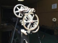
I wonder if I can get anyone to share some photos of the gear train on their Barnes 4 1/2. I lost all of the pictures I took during disassembly.
 
I do check in sometimes...

DA8E9246-CA75-471C-B28B-D4CB55B25F8E.jpg

Did you get a change gear plate with either lathes? It will specify spindle, stub, and to screw gear location for feeds, and threading

CAUTION!!! largest gear 104T on screw tends to get broken easily, and will attract loose clothing!!!

Remember there are NO safety’s designed into the drive system. When overloaded, the weakest link BREAKS!!! A drive belt, that is loose enough to slip, could be a life saver.

Also, reversing a screwed on chuck can be exciting!

Ray :D
 
Thank you very much. It was actually much simpler than I expected. I just looked at the plate and it came together easily.

I have one gear in my pile of parts that I cannot figure out though.... I actually wonder if it even goes to the lathe or maybe got mixed up with the change gears at one point. The gear teeth are eccentric to the bore. That doesn’t go to this lathe right?
 
Barnes seats are characterized by a "5 sided" hole in the very center of the seat.

aw47k_1_.jpg


There are other "similar" seats out there, probably by the same foundry which cast the barnes seats.

Not that scarce and have been reproduced. I bought a cast iron seat from a reproducer who for a time was reproducing the Barnes velocipede jig saw in aluminum of all things. But his seats were available separately and even included the unusual square taper head bolt to hold it to the underarm.

Another Barnes seat I scored from a Craigslist "seat collector" who was thinning his collection. Included was the seat underarm which are reproduced as well, but these were original. I paid $60 for both which is well as I needed both.

So they can be had. If you want one just like the one you show for $40 plus your postage (I'll get what I have in it minus my postage) I'll sell it to you as I probably won't ever be using it. I will observe that these "aftermarket" seats are a little more "robust" than the original Barnes seats which tend to be fragile. Although the pattern is "close." Maybe robust is a good thing - if it looks like the original mostly.

Joe in NH
 
Does everything appear to be in order on mine?

As a "straight thru" geartrain, you're fine. You have used a small gear as a "place keeper" on the stud bushing - which is fine. The spindle has its "ring spacer" on the outside which is fine too.

You want everything to line up with the "single gear capable" inboard position on the lead screw. If you do compound gearing then the spindle gear moves to the "outboard" with the spacer on the inside. The stud bushing is similar and uses two gears in ratio per the gear train chart. Note the only function of the stud bushing is to keep the two intermediate stud gears "together" when used in compound gearing.

Hence the English language nomenclature of being a "stud gear" - as in being a business entity which everyone else revolves around and is essential to keep business moving.

Note also for "ordinary" turning, you put the LARGE gear (whatever yours is) on the lead screw to give very fine advance to the lead screw. Use the "next largest" gear as the stud gear. I think this is outlined on the gear chart.

Joe in NH
 
Thanks joe.

In his description said it was marked Barnes Rockford Illinois.

I thought the lead screws were not supposed to be used for plain turning?


Back
Top