JHolland:
Thanks for posting clip of the German battleship. The day-to-day life on board a working ship is something most people do not think about. The detail of breaking ice off the deck, hand rails, lifeboat falls and all else looked like an endless job in arctic waters. Strange to think that ice build-up would be sufficient to raise a ship's center of gravity and affect ship stability.
As for the steering mechanisms of ships, it is a whole interesting subtopic. I am also intrigued by it, coming from many years' experience in hydroelectric plants. The servomechanism to move and set the position of turbine wicket gates (similar to rudders) or runner blades (on Kaplan type turbines, which are essentially "variable pitch propellors") is a very close parallel to the steering gear of a ship. The turbine governor, or gate position limiter "call for" a gate position. The servomechanism "answers" by moving the gates to the required position. In the process, a "restoring rod" or cable (on mechanical/hydraulic systems) moves with the gate servo and "neutralizes" the servo when the required position is reached. A position indicator is usually on the governor cabinet, and another remote one is up in the control room.
Most of the wicket gate servo mechanisms are large hydraulic cylinders, working the gate control ring in a "push-pull" arrangement. The gate ring moves through a sector of arc, much like a ship's rudder stock. The hydraulics for supplying oil to the wicket gate servos require too much oil flow for pumps to keep up, so large accumulators (air-over-oil on very large units) are used.
The "distributing valve" is what takes a small mechanical movement from the governor output and uses it to "move the pilot valve off center". This sets the "stop" and with the pilot valve off-center, oil is ported to the main distributing valve which provides a massive oil flow to the servo cylinders.
Interestingly, the a ballhead-hydraulic governor will use a very small hydraulic system within the governor itself having its own pilot valve and distributing valve to work a small servo. This servo within the governor will drive the output shaft or linkage connected to the pilot valve on the gate (or rudder) servo system.
Aboard a ship with hydraulic steering, the wheelsman turns the wheel and a pointer, following the ship's wheel, swings to the required new rudder position. The ship's helm is connected to the steering gear by either shafting, or possibly on larger WWII vessels, by something like "Selsyn" motors. Either way, the moving of the ship's wheel will unbalance the pilot valve on the distributing valve for the rudder servos and set a "stop". The unbalanced pilot ports oil to move the distributing valve's main valve, and oil is ported to the rudder servos. As the rudder begins to move, a second pointer on the rudder position indicator (one at the steering gear, one up at the helm) will move as well. When the rudder reaches required new position, the pointers will cover each other, and the pilot valve in the distributing valve is again "neutralized" or "centered".
At the pumped storage hydro plant I retired from, we had huge servos to move the wicket gates, somewhere around 36" bore, and the piston rods were on the order of 16-18" diameter. We had equally huge air-over-oil accumulators. To provide oil pressure, Woodward Governor had used deLaval-IMO gear pumps with maybe 25 HP motors. These made a racket, and other than very slow moves of the gates done on the "auxiliary" valves for checking gate settings or position indicator transducer calibrations, there was no way the pumps would keep up for a real gate move.
I was always amazed that the small movement of the governor output could cause the huge servos to respond precisely. It was a case of hydraulic amplifiers in series.
Later on, we went to digital governors, but these still worked a distributing valve and the original servos were still used.
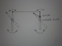
The screw you saw aboard the battleship may well have been a part of an emergency steering gear, or some means of positively holding the rudder in the event of damage in battle. Rather than have to quickly turn the screw to bring a travelling nut to a position to match the rudder , a small high speed auxiliary motor likely drove that lead screw in synch with the hydraulic servo drive. In the event of the main steering gear becoming disabled through battle damage or system failure, a heavier geared motor drive would be clutched in. This would be the primary emergency steering gear. The rudder could still be controlled from the helm on the bridge or an emergency steering station. If that motor drive failed (if the ship lost all electric power, or power distribution to the steering gear compartment was knocked out), then the crew would de-clutch the motor drive and turn that lead screw using large hand wheels and probably some reduction gearing. This gave rudder control, but likely took a gang of men forever and a day to make each change of rudder position.
I know in the days of steam, aside from the more usual "steam steering engine" using a drum and chains to move the rudder quadrant, there were screw type steam steering gears. On the Great Lakes, aboard the old railroad car ferry "Chief Wawatam" (1911-1988), they had what a steam/screw type steering gear. Some of the crew referred to it as a "battleship" type steering gear. The "Black Chief" as she was known, was also an icebreaker, and was usually chartered by the Great Lakes Carriers Association to break a channel to open the uppper Great Lakes in the spring for the start of the shipping seasons. As such, she was built a good deal heavier than most vessels, and had a forward screw (propellor) under her bow. Whether the steering gear was chosen for a quicker response or because the chances of damage in the heavy ice might break steering chains are both possibilities.
My own experience with ship's steering gears is quite funny. In 1986, I was assigned to a jobsite where we were dredging the bed of the Hudson River for a submarine cable crossing as part of a power transmission line we were building. We had a disposal site about 25 miles up river from the dredging site, and the clay spoil from the river bed was moved upriver on coal barges by tugboats. We had a few tugs on the job, and I was the engineer assigned to the disposal site. We had a dredging contractor who setup a dredge pump (an ex WWII submarine diesel engine, GM 278A series, driving a pump aboard a barge) to handle the clay which was mixed into a slurry in the hold of each barge. I got a call to come down to the dredging site, and since I was not needed there until later, I hitched a ride on a tugboat heading downriver light. The tug was an ex WII US Army Transportation Corps ship docking tug, repowered with an EMD 567 series LST engine. I was up in the wheelhouse watching the world go by and enjoying an otherwise uneventful mild day. The wheelhouse doors were hooked open, and the skipper/owner of the tug was sitting on his bar stool (seemed like all the old tug skippers put a bar stool in their wheelhouses), smoking a cigaratte and handling the wheel with two fingers. The skipper looked at me and asked if I cared to join him in a fried liverwurst sandwich (the only guy I ever knew who went for fried liverwurst). I declined the sandwich, so the skipper asked if I wanted a mug of coffee, which I accepted. I figured he'd holler down the voice pipe to the galley for his sandwich and my coffee. Instead, he stepped out of the wheelhouse and said: "Take 'er, chief.... I'll be back with yer coffee". Before I could holler that I never wheeled a tug or any vessel other than an occasional pleasure boat, the skipper was down the ladder and into the galley below. That left me at the helm. I knew enough to try to keep the tug centered in the channel between the marker buoys. Of course, the tug wanted to sheer off to one side of the channel, so I cranked in some rudder. Since the tug was a diesel powered vessel, I figured she had electro hydraulic steering and expected a quick response or "answer" from the rudder. Instead, the rudder position indicator stayed where it was. OK, sez I, this tug is sheering too close to the edge of the channel and will wind up aground in the mud... so, I cranked in more rudder. Still no response, so more yet. About the time the rudder position pointer was damned hear hard to starb'd, there was a hellacious clanking and whirring from the after end of the tug. It was the steering chains "running out" as the steering gear "answered" and gave me full rudder all at once. Then I knew: this tug did not have electrohydraulic steering, but had some kind of electromechanical steering engine, just about what the old vessels on the Lakes had had, only electrically driven. Slow responding helm. I knew I was in trouble. That tug heeled like a motorcycle taking a curve and headed into a hard turn. I heard the guys below slamming the watertight doors to the deck house. I pulled back on the throttle (WABCO air controls as I recall, Falk reduction gear), and cranked plenty of opposite rudder in. The result was I was over-correcting and had that tug making "S" turns down the channel, pretty much a sine wave of diminishing amplitude. About the time I figured out the helm and had the tug centered in the channel again, the radio went off, hailing the tug by name. I grabbed the mike, since I was alone in the wheelhouse and hollered the name of the tug and "where away". "Look abaft of you 'Cap" came over the radio. I stuck my head out the wheelhouse door and saw a tanker, riding high and empty, coming down river astern of us. "One whistle side or two ? " was my next question, knowing I had to lay over and let the tanker pass. About then, the skipper appeared in the wheelhouse door with my mug of coffee, laughing fit to piss his pants. He took the wheel and I cussed him up and down, and he kept laughing and said it was time I learned to wheel a tug. I went after and down into the engine room to the steering gear flat. Sure enough, there was the original electro-mechanical steering gear. It was a close cousin to the old steam steering engines, having a DC motor instead of a steam engine. I stayed below and watched the steering gear for some time after that to get an idea of how it answered the helm. It was SLOW when compared to a hydraulic steering servo.
That tug skipper gave me a parting gift of a 1957 copy of Bowditch's American Practical Navigator he had in his wheelhouse, and told me to loosen up and try fried liverwurst. I have not done either in the ensuing 33 + years.
As I worked around the hydroelectric plants, I was always struck by the similarities between ship's steering gear and things like gate positioners and governor
hydraulics. On a ship like the German battleship, it would be almost impossible to work the rudders with steering chains. In addition, an electro mechanical or steam steering engine would give a kind of sudden response and sudden stop to the rudder movement, while the hydraulic servos likely provide a smooth acceleration and deceleration to the rudder movements. I saw this with the gate servo hydraulics on the hydro turbines. The lead screw steering might also have been too slow a response for maneuvering in battle, and over the course of a voyage and battle maneuvers, might well have worn out a few of the travelling nuts on that lead screw.
The drive of the lead screw in the youtube clip was likely an "auxiliary" motor which turned the screw at a fast rate to keep up with the hydraulics which made the actual rudder moves in regular service. With next to no load on the travelling nut in that mode of operation, the travelling nut was going to last a long time.