What's new
What's new

Best end mill for slotting with my B&S #2

99Panhard

Stainless
Joined
Feb 22, 2006
Location
Smithfield, Rhode Island
I tried searching on this question but everything I found pertains to much newer machines. I have to cut slots in the rotor of the rotary vane oil pump I made for my 1910 Mitchell. The slots will be 1/4" wide and .400 deep. The maximum speed of my vertical head is around 1300 rpm. I'd like the slots to be as smooth as possible since the vanes have to slide in them.
 
Perhaps a sketch or picture of the part you are making and the material you would like to cut would help give a better idea what to suggest.
A couple of things that crossed my mind,
If the slots go right through a round body maybe you could use a small diameter fine pitch ,1/4” wide plain or side tooth milling cutter on a stub arbour or a 1/4” wide woodruff key cutter large enough in diameter to let you in .400 in the vertical head on the side of the piece .
These could maybe produce a good finish at a lower R.P.M.
If cutting with an end mill you could maybe rough the slots with a cutter that has been sharpened down several thousandths and making several cuts until the .400 depth is reached and then cleaning up with a new 1/4” cutter .
I’m thinking a 1/4” end mill might tend to flex and cut oversize if you tried to cut a slot in one cut .

Regards,
Jim
 
It is a horizontal mill with a vertical head so I could set the piece up with the dividing head on the table. I hadn't thought of that - largely because I usually use it as a vertical machine but switching it over isn't an impossible job - I think it takes about 20 minutes. Here is my drawing... I aplogize for it not being very professional. I use the graphics program I use to design books, never having mastered any of the real drawing programs. The rotor is just a tiny bit smaller than 2" in diameter. It will run on the back end of the camshaft. The pump is designed to replace the rear camshaft bearing. The camshaft is 1" in diameter - the other two black rectangles are the set screws that will retain it.

Rotor.jpg
 

Attachments

  • Rotor.jpg
    Rotor.jpg
    30 KB · Views: 61
Here's two photos of the pump on its test bed. It is running in these pictures and pumping although I think its performance can be improved. The vanes in this first version have little compression springs behind them and I suspect one of the springs has broken because after running about 4 hours it has developed a slight clicking noise. Ideally, I'd like to do away with the springs and rely on centrifugal force. In its finished state the pump will be unreachable without removing the flywheel so it won't be easy to repair if it fails. I don't plan to take it apart for another week or two as I want to finish the job I currently have on my bench first.

Oil Pump 2.JPG

Oil Pump 1.JPG
 
Milling cutter should leave a pretty smooth finish on the sides of the slots. Maybe try a leaf spring to push the vanes out?
 
I've been trying to find an appropriate leaf spring, without any luck so far. Of course, there are lots of companies that would like to make them but that is pretty much out of the question when you need 4 of them and maybe a dozen more as spares.
 
If you can find a suitable small 1/4” wide cutter you could hold it on a stub arbor and still hold it in your vertical head and cut the slots from either the front or back side of the part instead of the top as you would on a horizontal arbor .
Not the best setup but maybe you will get some Ideas from the attached picture showing the woodruff key cutter that could be used to slot the nose ring and the other small cutters on home made arbors from my collection .
P.S. an 812 Woodruff cutter is 1.5” dia. with 1/2” shank x 1/4” wide so you should be able to cut .400” deep with some to spare.
Just an example for reference you can probably find from your regular supplier.
812 WOODRUFF STAG/TOOTH
 

Attachments

  • DSCF8414.jpg
    DSCF8414.jpg
    95.9 KB · Views: 87
If the slot goes through from one end to the other the best way to keep it straight is with a slotting cutter, not an end mill. Might try to find one a couple of thousands under size with staggered teeth so it will cut on both sides, sometimes I slip some paper between the spacers and the cutter so it will cut the right width slot and it can be done in one pass. I would test it on a piece of scrap before calling it ready though.
Dan
 
I'm feeling a little dumb for not thinking of using the horizontal mill as a - horizontal mill. I have quite a lot of cutters so tomorrow I'll go through them and see if I can find someting suitable. I'm sure I can because the actual width of the vane can be anything from 1/4" to 3/8". I'll also try it out on a piece of scrap before first.
 
Trim a piece of blue steel banding (stuff for strapping things to pallets etc)and bend it to suite for your leaf spring. I believe it is something like 1095 Maybe? Should be decent for what purpose it will serve in your application. Just an idea.
 
I've been trying to find an appropriate leaf spring, without any luck so far. Of course, there are lots of companies that would like to make them but that is pretty much out of the question when you need 4 of them and maybe a dozen more as spares.

McMaster-Carr sells some flat spring steel in coils. I bought some 1/4 wide to make a new point spring for the magneto on my '32 Farmall tractor. I can cut a couple lengths off and send you some in the mail to see if it will work if you like. I cannot remember what thickness I bought, (.010 I think) but it is available in different width and thickness for a variety of springiness and can be formed or bent to shape.

Warren
 
I'm going to try to see if I can make it work without the springs first. My concern is that the spring could break and, if it is behind the vane, could possibly jam it and the pump. I'm not sure what the result would be but it wouldn't be pretty and the engine would have to come out to even get a good look at it. So, if I use springs, I'd want something that was made to withstand the number of cycles these will have to undergo. The maximum RPM of the pump is probably 1000. It runs at half crankshaft speed so, for this engine, a consistent speed of 500 to 600 RPM is more realistic. At 500 RPM, the spring is being compressed 30,000 times per hour so to achieve any longevity in the pump the springs have to be capeable of millions of cycles or I have to be able to insert them in such a way that if they fail it won't damage the pump. If they failed by simply going flat, that would be no problem.

Warren, I've looked at the McMaster spring steel. In fact, I almost bought some but I've very little confidence in my ability to harden and temper a really durable spring so I held off looking for someting from a regular manufacturer. I have a few possibles but think I'll try the springless version first. I have seen a video of a rotary vane pump for viscous liquids (like oil) that worked on centrifugal force alone but whether I can replicate it in miniature is another question.
 
I think you will need springs. Centrifugal force at your small radius, on a light vane, at low RPM will not be much.

You can buy the clock spring steel already tempered. The hardness will give you the strength, and the strength will give you the fatigue limit. Calculating the stress for a half-elliptic spring should not be too hard to look up..Should be the same as a simple cantilever beam, at the center.

If you make your vanes with a bump in the middle of the inside edge, and make the slots deeper in the middle of their length than at the ends, you do not even need to arch the springs.
 
Thanks, that is a good point that I hadn't thought of. I'll still try it but will make the vanes as wide (and as heavy) as I can. If it doesn't work, I'll be in a better position to incorporate springs behind them.
 
It's hard to believe I did this thread almost a year ago... I took the advice above and cut the slots horizontally. It gave a much better finish than the end mill I'd used previously. I'll add these pictures of the finished pump.

IMG_1238.thumb.JPG.32b8ea4c43441864f83153b20aa10b33.jpg
 

Attachments

  • IMG_1238.thumb.JPG.32b8ea4c43441864f83153b20aa10b33.jpg
    IMG_1238.thumb.JPG.32b8ea4c43441864f83153b20aa10b33.jpg
    51.7 KB · Views: 54
  • IMG_1295.JPG.94161fab15d18db997843cdec48a9a9a.jpg
    IMG_1295.JPG.94161fab15d18db997843cdec48a9a9a.jpg
    37.1 KB · Views: 52
  • IMG_1635.thumb.JPG.820b1e1abb9a2d2cb00e917163fae132.JPG
    IMG_1635.thumb.JPG.820b1e1abb9a2d2cb00e917163fae132.JPG
    80.4 KB · Views: 57
  • IMG_1637.thumb.JPG.5d4fca7904a0f467d3e9c6853b4aef30.JPG
    IMG_1637.thumb.JPG.5d4fca7904a0f467d3e9c6853b4aef30.JPG
    73 KB · Views: 52
I tend to look at a job like slotting the rotor of this vane pump by asking myself: "How would this part have been machined back in the 1900's ?". The answer is: most likely by means of a horizontal milling machine with a milling cutter 1/4" wide. In the 1900's such a cutter would be made from high carbon tool steel, as even high speed steel cutters were not in use, let alone carbides. A 1/4" wide milling cutter, perhaps ground a touch narrower than the final required width might have been used. The slots may well have been hand finished by filing to get the right fit and a smooth surface on the walls of the slots.

The era the Mitchell car was made and the car itself was not the era of large numbers of mass-produced automobiles. The car and its engine were built right around the time the Model T was getting into high production numbers. Most car builders were small and building their cars as almost one-off type things. Most of those small car builders did not survive into the era of making hundreds of cars, if not more, each day. It was an era when hand labor as part of the manufacturing processes was a given, and an era when the use of files to produce finished work was commonplace. My mind, in going back to this era, sees rows of bench vises and men using smooth-cut files to hand finish the slots in the pump rotors.

By way of a similar example: Indian Motorcycles, into the late 20's and early 30's, had great dimensional variations on certain machined surfaces in the crankcase halves and even on the crankshaft assembly (flywheels and crankpin) and connecting rods. Building one of those engines on the "production line" called for individual fitup of the parts, checking the fits, possibly having thrust washers surface ground to suit the as-assembled dimensions, and adjustments which included the use of lead hammers to true up a crankshaft. The Mitchell cars were not built in the numbers that Indian was building motorcycles, so hand filing of the rotor slots to fit the oil pump vanes would be highly likely.

Using pre-tempered clock spring material is a thought I also had for the leaf springs to hold out the vanes. When I first read the thread, I thought of using strips cut and ground from carbon steel bandsaw blade for the springs. I've made some light spring leaves for one-off jobs from scrapped carbon steel bandsaw blade stock. As I read further, I realized how small and light the springs have to be, so bandsaw blade material is way heavy for the job. "Blue Steel" clock spring material would have been in common use back "in the day", and is still available.

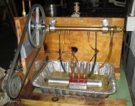
In reading this thread, the fact the Mitchell had an oil pump, let alone a vane type pump, in the era it was built is quite remarkable. Most auto engines of that time period had splash lubrication, or used "total loss" oiling for some of the working parts. Seeing what appears to be a fairly husky vane pump for the Mitchell engine's lubrication system says a lot about the design of that engine for the times.

On various jobs I get into, I find myself looking at certain parts or assemblies- whether they be machine work, or locomotive boiler work, to name a couple of types of jobs. In looking the jobs over, whether for determining "fitness for service", or designing repairs or alterations, I find myself asking: "How did 'they' build it back then ?". Some of the work I come across borders on the impossible and would have called for some real slick maneuvering, such as riveting some of the seams on a locomotive boiler firebox "wrapper" with the firebox in place. Some of the work called for silver brazing in an era predating oxy-fuel or TIG torches, and some of the machine work is plainly quite amazing for the machine tools and cutting tools available back then. It is easy to lose sight of the important role that filing and hand-fitting of machine parts played back in that era. Legions of men spent their working lives "at the bench", hand filing and fitting parts and hand assembling them.

The making of a machinist back in the day usually required a number of filing exercises, filing to dimensions and getting things square and parallel and true, and getting surfaces dead flat or nearly so. Machine shops had a row of bench vises, usually along a wall with good natural light for the machinists or fitters. Mitchell likely had something like this, and it is easy to visualize machinists hand filing rotor slots, matching up a set of vanes, and assembling the pumps as individual units.
 
Joe... Mitchell didn't build the pump. The original "pump" was a box oiler on the side of the engine driven by a belt from the front pulley. The oil did not circulate. You kept putting it in until the car started smoking at which point you opened a petcock on the sump and drained the excess out onto the ground. They take a dim view of that today. It was already obsolete when this car was new and the next year they added a plunger oil pump. This pump is my own design, made to replace the large iron casting that supports the back end of the camshaft. The Mitchell (or at least its engine) was, to my mind poorly built. I suspect the engine design was a rush job and that they could only meet the price they were advertising by cutting every possible corner. This engine was only used for two years so I expect it had a lot of problems. In any case, I've no interest in knocking myself out copying something that wasn't very good to begin with and should I ever finish this project I'd like to be able to drive it some distance. The vane pump idea came from the 1911 edition of P.M. Heldt's "Gasoline Automobile" a two-volume engineering manual for engine designers. Vane pumps were used on a few cars although in 1910 the plunger pump was more common.
 
Last edited:
I would suggest using a 7/32 end mill and creeping up on the .250" and making the last cuts climb cuts. Possibly roughing out the cuts even with a hacksaw before getting to the mill. A few cuts of increasing depth with the 7/32" mill won't take too long though, then increase the width in small increments climb cutting until you get to size.


Back
Top