What's new
What's new

Brainard Small Hand Milling Machine

M.B. Naegle

Diamond
Joined
Feb 7, 2011
Location
Conroe, TX USA
So...
I picked up another project... It started here:
Help identify small horizontal mill
So now my bleeding heart is waiting for the freight truck. Luckily since it's practically a micro-mill, shipping wasn't too bad. Once it arrives, I'll get some new pictures.

I got it as it's the right size for my little shop at home. It's missing the spindle parts, but was fairly priced, so best case I'm looking to recreate the old step-pulley drive and run it off of the line-shaft system I'm putting together. Worst case, I can redesign a practical spindle for it. Given the number of projects I have going right now, I won't be starting on this one until I can get some other stuff done, but I wanted to start the research/planning process. I'd appreciate any help I can get from any other #5 owners out there.

Starting with what I know about the mill: It's a Brainard #5 horizontal mill made sometime between 1871 and 1899. The missing parts are long gone, and there are not many mills like it around to borrow parts or information from. Vintagemachinery.org has a Brainard catalog with a couple paragraphs about this mill and one small picture. It says that this mill was designed for light duty brass work, such as for electrical components, so there never was an over-arm support or a back-gear.

The spindle had a cone pulley drive with five steps and the catalog gives good information for what RPM was needed to drive the machine. With that I'll do some math to figure what the speeds were and dimensions of the missing cone pulleys. The spindle rode in bronze bearings which are still in the head-stock, so all that really needs to be made is a cone pulley and a spindle. I'll get some figures by scaling the cone pulley in the catalog picture and see if there might be a cone pulley set from another machine like an old lathe that could be adapted. IMO the spindle would be easy to produce from some kind of tool steel. Ideally I'll grind the bearing surfaces and tool register to be concentric. I'm guessing Brown and Sharpe #7 would be an appropriate tool taper, and it's one I'm well stocked in end-mills and misc. holders, I'll just need to piece together another set of collets.

The knee, while not on the machine, seems to all be there with the exception of one bolt-on gib to hold the knee to the column, one ball crank, and the vertical adusting wheel and screw. All of which should be easy to replace. Some pictures online of similar mills show a power feed mechanism that hung off of the back of the spindle, but I'm not certain that this one had it as the table doesn't seem to have had it's half of that system, so hand-feed only.

The side door is missing which is sad, but I'll make something out of a plate of steel to fill the hole. Perhaps one day as 3D printing and casting technology get more economical and easy to work with, I can model up a raised letter door and replace it. This picture is not of my mill but was posted in the prior thread.
Brainard No.5 18.jpg

I'm already in the process of building some smaller overhead clutch jack-shafts for my tool-and-cutter-grinder and bench grinder, and I think this mill would use a similar size bearing/clutch set so I'll make one for it while I'm at it. The clutch I'm making for my Whitcomb Blaisdell lathe will have a reversing clutch so I might do the same with this mill too. Of course, I could simplify the drive with a DC motor or VFD driven AC motor hanging off the side of the column, and that might get it cutting chips sooner... but that's not as fun as playing with leather belts hanging from the ceiling.:) Also I'm not trying to DIY a little home-shop-machinist bench mill so much as complete a piece of history that could then be useful, which will involve some DIY by a machinist in a home shop. Semantics is everything.

The previous owner did find these pictures of the same model of mill on a different forum. Not sure who owns it but they're good reference for a complete machine.
tapatalk_1613828808809.jpg
tapatalk_1613828801584.jpg
More pictures coming when the machine arrives.
 

Attachments

  • 0116211624a_HDR.jpg
    0116211624a_HDR.jpg
    88.2 KB · Views: 264
Starting with what I know about the mill: It's a Brainard #5 horizontal mill made sometime between 1871 and 1899.

This is what I said in the other thread after seeing pictures of the other parts.
"It is the Small Hand Milling Machine and not the No.5.
The hand mill used most of the same castings as the No.5.
The hand mill was a production mill.
You have the original knee, saddle and part of the table, but all have been modified.
This never had a long T slotted table.
On top of the small table would have been a lever operated riser and a vise on top of the riser.
The knee would have been raised and lowered by a lever too."

The knee, saddle and table are different on this mill than on the No.5 mill.
The knee on this mill has had part of the dovetail way machined off or broken off (the side the gib would be on).

Send me your email and I can send a large scan of the catalog page of this mill.

Rob

Thanks! message sent!

Sorry I mis-read that. In all my googling, the #5 has been the closest model, so I'd be glad to see any scans of the actual machine so I can keep as much of the design original as possible.

Looking at the parts that are missing on this mill, I get the impression that a prior owner may have tried to update the mill, perhaps thinking to change the spindle to integrate a tread-mill motor or something:crazy:. Perhaps the old parts were modified or scrapped before they gave up on it or otherwise lost interest? It's all speculation on my part, but if possible I'd like to at least know what it used to be, and then IF I were to "update" it in some way (the table surface and vertical movement parts for example), I could do so in a way that didn't permanently change the machine.

Concerning the knee, if part of the knee is broken off, from the pictures I think that enough is there to make up the missing side and bolt it into the casting.
 
Brainard hand mill.jpg
Big thanks to Robert Lang! This looks to be exactly what the mill is. No model number, just "Small Hand Milling Machine":)

So this mill would have 4" travel vertically and Longitudinally that would be controlled via lever (I assume as some sort of cam/lever) pushing on the sliding components. Both have limit rods. The longitudinal travel rod looks like it was modified to be a screw feed. The knee cross travel would be screw feed and has 2 1/2" of travel. Not a big window, but it's enough with the right work-holding configuration. I imagine this mill could be set up for cutting small gears or similar work.
(pics from the other thread)
0121211134.jpg
0121211135.jpg
0121211134a.jpg
0121211135b.jpg

Tracking shows the ETA as Monday. We'll see as it seems that freight/parcel services are still catching up from the snow storms last week.
 
So this mill would have 4" travel vertically and Longitudinally that would be controlled via lever (I assume as some sort of cam/lever) pushing on the sliding components. Both have limit rods. The longitudinal travel rod looks like it was modified to be a screw feed.
(pics from the other thread)
View attachment 314917
View attachment 314919

I think both levers would be gear and rack operation.
You can see four holes in the front column ways for a rack.
It also looks like there is a recessed pocket in the saddle table ways for a rack.
That lever would have a large diameter gear on it.

Rob
 
Hey Rob I'm the one that sold him the mill. It appears that the other half of the dovetail was bolted on to the side of the knee but it didn't come with the mill so that is something that is going to have to be made. It didn't appear to be broken off
 
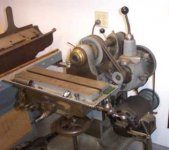
The Brainard has arrived!
20210301_181647.jpg
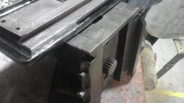
We'll start with the knee. The missing dovetail looks to be a simple bolt-on replacement. I imagine that the gib strip would be a separate adjustable piece so that the dovetail can bolt on solid. One piece that IS broken off is boss the vertical depth-stop rod. The rod would thread into the base casting and slip through the boss with am nuts on either side. I'm going to see if I can have the boss bolt to the replacement dovetail piece, then I don't have to mess with splicing it into the knee.
20210301_181815.jpg
20210301_181826.jpg
As far as the vertical rise goes, there for sure was a gear rack bolted to the column. The shadow of it being there is clear enough that I'll be able to measure the pitch and width for the replacement. I removed an unoriginal piece that looks like a prior owner trying to make a screw adjustment vertical rise. It was hiding a fine thread hole in the casting (the added bit wasn't threaded but but turned to fit over the threads). If this mill was built anything like my Whitcomb Blaisdell lathe which also came out of Massachusetts old industrial sector, then the fine thread in the knee casting was to accept a bearing hub for the gear rack pinion gear. At least that's how the apron was constructed in the WB lathe. Those pieces will all be easy to reproduce. The part I'm not certain about is that there is also a raised boss on the base casting that looks like it was for a vertical adjusting screw like on other small Brainard mills. Not sure how that would connect to the gear/lever vertical adjustment mechanism, and there's already a depth rod on the right side of the column. Perhaps the base casting was machined the same as the #5 style mill, but it was assembled to be the production mill?
20210301_181718.jpg
20210301_181704.jpg
 
20210301_181844.jpg
The saddle cross travel is all there. The only thing I might change is that it originally just had a square nub for a loose crank to turn and someone turned it down to pin a ball crank on. I might go back to the square drive as I imagine that the removable crank enabled the other movement levers to move without you busting your knuckles.
20210301_181937.jpg
20210301_181957.jpg
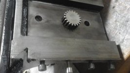
The table movement still isn't clear. The top of the saddle appears to be cut out to accept a gear rack, but I imagine it would quickly fill up with chips and be difficult to clean as you can't just brush them out the side. The gear rack would need to be bellow the top surface of the dovetail to clear the table sliding back and forth. The table doesn't have any cut out for a pinion gear to interact with the gear rack (other than a small hole in the middle). Given that the gear rack isn't centered over the saddle, but off to the side, perhaps the missing portion of the table had the pinion gear and lever off to the side and had some kind of cover to keep chips out of the gear? According to the catalog photo however, the pinion and lever were centered with the table. The cut out in the middle of the table where the screw can be seen is just a cast relief. I imagine that it's only purpose is to give space for the tables depth stop rod to go, without having to bore a long hole through the table. The current table movement screw does thread into one side of the table, but I think it was meant to have a jam nut there and it could be adjusted in and out, as well as having adjustable stops on either side of the boss on the right side of the saddle.

There's also a broken portion of the chip gutter, but this can be built up via brazing or at least reinforced bondo or epoxy.

Not sure from the catalog pictures of the original vise was integrated into the table, or if there was surface to work with, but I think making the top of the table with a T-slot or at least an array of threaded holes would be best. For my uses, It would be helpful to be able to change the vise orientation and change it out for an indexer as needed.
20210301_181726.jpg
20210301_181736.jpg
Completing the spindle is fairly straight forward. The front bearing diameter backlash is adjustable and the dust cover on the outside would go over a flange on the end of the spindle, with adjustable spanner nuts on the other side to set the spindles front-to-back backlash, the rear bearing of the spindle just floats. The missing cone pulley would be the most difficult to replace IMO as it's size would make it expensive to turn form a solid piece of steel. Unless I can find a similar five speed pulley to adapt, I think casting a replacement would be cheapest.

The ways and flat surfaces are all pretty pitted and rusty. I think re-scrapping it all will definitely be on the list of things to do, but Likely much later down the road. Once I have the spindle replaced, I can start by scraping the face of the knee to be truly perpendicular to the spindle and build it from there. No serial numbers found yet, but given the mills age I wouldn't be surprised if it never had a serial number.

This mill will be a fun project, but as I said before I'll need to finish some other stuff first, so I'll have lots of time to consider how to fill in the blanks, and be on the look-out for cone pulleys. You can see on the side of the column where someone had mounted a motor previously. While it is a practical option, I'd really rather go with the overhead drive set-up, so I'll need some time to get all the pulleys and hangers acquired and hung.
 
If you decide to put gear rack back on it, I have a few different pieces of various sizes and I may have some gears to go with it. I would give it to you for just the cost of shipping.
 
I've been sketching out the parts I'll need to make, using what parts are there for known dimensions and the catalog pictures to figure approximate sizes of bigger stuff. When I get around to it (I keep using those up), I plan to start with the spindle and vertical knee parts. The spindle I can make even without the pulley, and I'm thinking of making it with a Brown & Sharpe #7 taper with a driving key for tang tooling, and a through hole for drawing in collets, and I want to make or purchase a test bar in that taper. With it, I'll check that the spindle is square to the face of the vertical dovetail and scrape it flat before assembling the knee (will scrape the other surfaces as well as it comes together). The spindle is big enough that I could also do it in Brown & Sharpe #9, or a similar Morse taper, but IMO the machine isn't big enough to utilize that size of tooling, and I'm already well stocked in B&S #7 shank end mills.

According to the catalog on Vintage Machinery, the jack shaft for the #5 Braindard (which looks to have the same spindle) would spin at 130 RPM via a 10" diameter, 2 1/2" wide pulley. The belt running down to the machine would be 2". The original overhead clutch looks to have been a simple slip clutch using two side-by-side pulleys, one loose and one set on the shaft, and rod with fingers to slide the belt back and forth. I also have a couple clutch assemblies salvaged from other machines, one with a tapered iron cone clutch, and the other with a tapered composite face, both of which look like they would easily power the mill and would mean less from-scratch fabrication, but one is on a 6" diameter pulley and the other is a 6 3/4", so If I were to use one of them I would need to adjust the required RPM's coming into the clutch, which all depends on what pulleys I have in my pile. The other possibility would be bolting some wood segments over the pulleys to build them up to the right diameter. If I were to stick with the slip pulley design, I have several 12" flat pulleys that would work with adjusted RPM's. I'm not going to bother with a reversing clutch/spindle. If I need to run it reverse, I'll keep a second slightly longer belt hanging on the counter shaft that I can run with a twist in it.

Concerning the cone pulleys, the largest pulley looks to be the same diameter as the driving pulleys on the countershaft (10") and it has a total of 5 steps/speeds going progressively smaller. Unless someone with big lathe down-time wants to help, a 10" solid round is a little out of my desire to hog out, so I'm going to wait and see if something I can re-purpose turns up, but at this point I think casting the cone pulleys will be the best route. A 10" casting I can do as it'll already be lighter and not take as heavy of cuts to finish. While I'm at it, I also need to replace two other pairs of cone pulleys on our Brown & Sharpe #12 mill (one set for the feed and the other for the spindle), so I'll get some practice. The upper pulley I could make from hard Maple, but the spindle pulley IMO needs the mass of steel or iron, but If I'm making one, I can make a pair.

One task I've thought this mill could be hand for is cutting gears with a small indexer, but to do so I think I'll need to do some form of outboard arbor support. I've been keeping that possibility in mind designing the parts, but were I to do it I wouldn't want it to do permanent modification to the machine such as bolting an overarm to the top bearings. I'd make it with adjustable height and clamp onto the top of the knee. It wouldn't be a very universal arbor support, but this machine never was to begin with and I don't intend to make it so, at least not permanently. IMO it'll better serve doing what it was designed to do, high volume simple tasks reliant on fixturing.
 
Take some accurate measurements of the cone pulleys that you need and I will look to see if I have anything that you can use.

Thanks! The counter-shaft driving pulleys, which look to be about the same diameter as the largest step on the cone pulley, would be 10". I measured on the machine though and 10" won't fit in the frame. 9" could do it though with just enough room for the belt, so by my math I'd be looking for a pair of cone pulleys that are about 10" wide with five 2" steps measuring 3", 4.5", 6", 7.5", and 9". There's no back gear so the hubs would be simple, likely with a key way and set screw to mount. I'm also assuming the two pulleys are the same size.

I'll need to revisit my notes on the Brown & Sharpe #12 and get back to you for it's cone pulleys.
 
Gathering materials, I don't have a piece of tool steel big enough on hand to make the spindle and I'm not exited about what it would cost, but I do have some 1018 mild steel that would do the job, so I'm leaning towards making it case-hardened. My plan is to rough cut all the dimensions a little big, then finish bore the tool taper and use a B&S#7 plug to support and drive the tool end while I cut all of the outside dimensions. I'll then heat treat before the final pass, but I don't have cylindrical grinding on hand, unless I decide to wait for the Cincinnati Tool & Cutter Grinder at home to come together, so my alternative at this point would be to cut all of the OD dimensions (except for the take-up nut threads) half a thousands large, heat treat, then hand polish to size. In the end, the only critical stuff would be getting the two bearing surfaces and the tool register smooth and indicating within .001", which isn't difficult.

The vertical knee adjusting parts are coming together too. The gear and gear rack measure to be a 12 pitch by gauging the "shadow" left on the face of the knee. It's not heavily worn, but there is some corrosion where moisture was trapped under the knee for awhile, which is why I want to scrape it true again. I measured where the gear and gear rack would be located in relation to the corner of the dovetail and got some good figures. I have 12 pitch spur gear on hand that's a little bigger than I want, but there's room to shift the rack over for it. The rack uses a couple 5/16-18 counter-bored screws and two 1/4" pins to locate, so once I have the parts mocked up, I'll mount the rack with the screws first, test fit it, then transfer the existing dowel pin holes in the column to the gear rack.

The spur gear I'll pin on the end of a 5/8" shaft with a 1/2" square drive at the other end. It goes through a long bearing that threads into the knee with a 1 1/2-14 thread. Iron would be ideal for that but I want to bore it over-sized and press a couple bronze sleeves in the ends, so steel would work for it as well. I plan to make it with a shoulder and a pin spanner hole to tighten it into the knee casting.

Last night, I worked on machining a pair of 18" dovetail straight edges I had cast. I got the pattern for them in some tool trading a couple years ago and wanted to make a finished straight edge with it to see how the design feels (but I'm not planing on making them for sale). My 'small' straight edge now is a King 24" dovetail, which I was using to re-scrape the Cincinnati Tool & Cutter Grinder that has a similar sized knee as the Brainard. The 24" King SE is a really good design, but it's a little big for these knees, so I want to finish the 18" and use it. The 24" will still get used on the Cincinnati's table and on other jobs. I also have a small rectangular cast iron surface plate that I'll use to check the over-all flatness of the face of the column.

Machining the parts for these machines is happening at work in my off time before coming home, but the scraping I can do at night once the little ones are in bed. I'm at a transition point in life where I've got kids that are starting to be crafty and creative, so I'm cutting back on late nights at the shop and trying to set the stage for having more fun at home. I have a bad habit of loading up on rebuild/restore projects, but in the last couple years it feels like I've been catching up and getting a rhythm. I'm looking forward to having these machines able to contribute so when one of my kids wants to make something "new", the tools and time are there. I grew up playing in my dad's garage shop where he made a living, but did so on his own so a little kid wasn't in the way. That shop has now transitioned into a bigger company a mile down the road from home, so my garage and evenings are going to become the playground for my kids. Even if they don't pursuer a career in it, I think it's important for kids to learn the possibility and joy that comes from being able to make something yourself. It has a positive influence on their problem solving abilities and creates a positive outlook on the world, more-so than what they get from TV and toys. My kids have a work bench that they can beat on stuff with and love building toys, but soon I want to start them on the "real" constructive things like wood and metal working.
 
I started a separate thread for the making the spindle as It could be a bigger challenge: https://www.practicalmachinist.com/vb/antique-machinery-and-history/thoughts-reproducing-pre-1900-spindle-396211/#post3835517

A couple of bits of progress though: I found an iron cone pulley! Well, one that will work for the upper shaft. The largest step is too big to fit into the headstock, but it'll work for the overhead shaft (which it looks like is what it's original purpose was). I'll get some pics of it, but I'm thinking that as long as all four steps are the same ratio, than I can make my headstock pulley a smaller diameter. For that I'm looking at two options: make a pattern and cast it, or make it from a weldment of pipe and flat rings for the larger steps, and solid steel for the first step and the center hub, turned to size after assembly. Not yet sure of how it will mount to the spindle, but I'm thinking of using a large woodruff key and a couple set screws offset at 90 degrees. The spindle's drawbar bore means that pinning the pulley on isn't an option.

I also made a few of the simpler parts for the knee elevation. Pics inbound.

Besides this case, I have three other big machine projects in the works at the moment: refitting the saddle on the 16" Hendey, rebuilding the Cincinnati Tool & Cutter Grinder, and setting up my line-shaft power plant and hanging the shafting. All boil down to time, but chipping away at the simpler tasks gives some motivation for the bigger ones.
 
20211105_073630.jpg
20211105_073621.jpg
Here's the cone pulley I found. It measures about 9 1/2" at the largest OD, but 8" is about all I can swing in the frame, so this one will do for the overhead pulley and I'll work out something else for the lower.
20211104_155359.jpg
Here's the vertical adjustment parts (pic taken before I threaded the end of the shaft). Parts like this I'll squeeze in when doing similar ops throughout the day. The original was likely a cast iron sleeve with a steel shaft, but this one is all steel with a couple bronze bushings between the shaft and the sleeve. Rather than rough these pieces out of larger bars, I made the larger diameters from shorter bits and pinned or hard-press-fit them together. The sleeve worked out as I had a length of tube with a 3/4" bore, so the bronze bushings made up the difference with the 5/8" shaft and there's an oil cavity in the middle. I'll likely make a little topper for the oil hole at some point to keep junk out. I wanted to get this assembly together so I can confirm positioning for the gear rack, as the new pinion gear I found was a little larger/more teeth than what I measured the old one to be, but I should have enough room to shift the gear rack to the side to compensate. The next steps will be mounting the gear rack to the column and recreating the missing knee dovetail and gib. The hand lever for this axis I'll hold off on as I'm hoping to find something close that I can repurpose. In the mean-time, I can mount a flat bar or generic hand wheel in it's place. It looks to me like the lever didn't have any key or pin and was just held on via the hex nut, that way you can position it wherever you like based on where the knee is at and how far your operation moves it.
20211104_174940.jpg
I also fixed the cross travel screw crank. After removing the ball crank the prior owner had pinned to it, I found that they just turned the end of the square shaft down to fit it, so I bored out a piece of 1/2" square stock to fit the void, welded it in place and ground it smooth again. Also located a crank to go with it. The vertical movement lever will need to be offset a little to miss the end of the cross travel shaft, unless I just make another longer shaft for the vertical movement.
 
More thoughts I've been mulling about with the table: The catalog photo clearly shows the table longitudinal movement handle to be in the middle, but the part of the table that remains on this machine shows that wouldn't have been possible, and the gear rack is offset left on the saddle. I suppose that in the section of the table that was fly-cut away, the table movement pinion gear could have not mated with the gear rack directly, but rather had an intermediate gear, but IMO that would create needless slack and complexity in the movement, AND it places the gear rack in a place that will accumulate chips.

I think this machine was different and had the pinion gear on the left side of the table, not the middle, and I think it actually had a table longer than the remaining section, with the gear rack protruding past the slot in the saddle to give the table equal amounts of movement to the right and left of the spindle. The longer table would have covered the gears and ways from chips, and made full use of the saddles dovetail. If the gear rack was only as long as the slot in the saddle, a section of the ways could never be used (and wear shows otherwise). Moving the gear movement to the left also allows it to be longer without interfering with the stop rod on the right side of the table. Perhaps there was a generational change, or this was a custom job for the original purchaser?

The catalog machine shows an integrated vise over a very short table. Not sure how the top of my original table was arranged, but I assume it was likely some kind of custom fixture and that's why it was removed by the prior owner. I have a plate of 1" cast iron that I'm thinking will work to rebuild the table surface and I'm thinking about doing it in a fashion similar to our old Brown & Sharpe #12 production mill with a single T-slot down the middle and an array of threaded holes down either side of that.
B&S table.jpg
I kinda like their approach too of instead of cutting a T-slot out of the solid plate, constructing it with steel plates on either side of the slot. It's easier to machine and more durable IMO.

The gear/lever movement of the table wouldn't work well with long travels, but a longer table enables more room for set-up, such as my gear cutting hopes, and if I did want to take a long pass, it would be easy to replace the lever with an optional handwheel.
 
I found a serial number on the mill. While getting the missing parts drawn and replaced, I've been media blasting and wire polishing the original parts. The front surface of the knee (same surface that the cross travel screw goes into) was painted over, but now clean it has #211 stamped on the left corner. Given the mills 1870's to 1890's time frame, I tend to think this was an earlier machine.

I've seen other machine manufacturers of this era use the same number sequence for all of their machines lines, and others that had a different sequence for each model. I'm not well versed with Brainards history, but in a 30 year time frame, I don't think they would have made over 5000 mills total, and most I think were the more standard models. From my experience, the first 5-10 years of a machine line sees a moderate increase in sales/production and the next 10-30 years are the 'Hay Day' of the machine. After that it gradually tapers off and the machine is either replaced by a newer model or becomes a legacy machine that is still sold/built in a much smaller capacity. There are always exceptions to this, especially when considering machines built in war time or that are cutting edge technology, but in general this has been my observation. I've also seen many companies start with machine #100 or #1000, not #1 in serial sequence, I think as a way of avoiding people adding digits and confusing numbers, which likely wouldn't happen if you owned the machine, but if it was leased or owned by the bank...

I'll also add that the ways on the mill aren't great... but they're good enough to get it going again. Lots of pitting and gouges, but the wear at least tells the tale that the machine was evenly worn down. It didn't only ever run one job and develop a dish in one spot. The top and bottom of the knee shows signs of hammering on the back near the vertical column ways, so I imagine that the operators forced a lot of movement due to lack of lubrication and not cleaning chips away. Kinda par for an old production machine I think, but it's interesting to see the proof of it.

(pictures inbound)
 
Here's the serial number on the knee.
20211116_075821.jpg
Here's the hammer damage on the back of the knee. Also the broken chip/drip rail I reformed with J.B. Weld (since it's not structural or mechanical, I didn't think it needed to be welded. I've done the same repair on a couple of other machines with good results).
20211116_075633.jpg
An example of the wear on this machine. It looks like at some point it spent a significant time in the dirt as the front of the knee appears the most pitted and portions of the ways are ok that were likely covered with another piece or thick grime, while others are very pitted.
20211116_075701.jpg
I also got the table gear rack finished and installed. The saddle has to be off to put it together and every time I take it apart I have to drive a taper pin out of the cross-travel screw. The added length of the gear rack is from my measurements determined to give the table full travel in both directions.
20211116_075752.jpg
 
Doing some figuring for recreating the missing table parts tonight. As I noted before, the table's gear rack position and length leads me to think that the table was longer than the catalogs advertised range of travel, so by my assumed measurements to get full use of the gear rack, and have the table move the same amount in both directions, I'm estimating a 15" long table (6" wide). The remaining original portion of the table is only 7" long, but 3 1/2" on each side isn't that much extra. The gear rack is about 11" long and I'd estimate it would give about 10" of travel, but the other 2 1/2" of table on each side of that travel would be helpful for set-up on either side of the work.

All that said, we have a big 1" thick cast iron platen in our material rack that I can carve the 15x6 table from, I believe salvaged from an old textile embossing press. It's squared up nicely and has a few holes in it, but measuring it all out I think they would all fall in places that would work with bolting everything together and providing fixture mounting holes on either side of a central T-slot. The plate is a little rusty, but it still shows tool marks from when it was plained long ago. I initially thought about surface grinding it flat, but it might not be necessary and the plained and aged surface would look much more at home on the mill. My only concern is that to cut the entire T-slot out of just the 1" plate, I'll need to put a 5/8" deep cut through it leaving only 3/8" on the bottom to hold it all together. I think it would be stable enough, but could warp or crack over time as set-ups are tightened to the top. The other option would be to "build up" the T-slot by adding 3/8" thick steel plates to the top of the table on either side of a 1/4" deep slot. Easier to machine and much stronger..... but I'd cover up that nice plained surface.:( The other option would be to bolt a solid 1/4-3/8" steel plate between the bottom of the new table the remaining original table, which might be the best compromise. Thoughts?

One last bit of math I want to measure out is how much usable knee travel I'd have with a 1" or 1 3/8" thick table added to what's there. It doesn't sound like much, but it might be a big deal if I'm adding a 1" to 3" thick vise base between the work and the table, or be the difference in how large of a round part can be indexed between centers. I guess If it ever came down to it I could cut a thinner fixture plate to take the new tables place, but as I'm trying to get it to be a fairly universal T-slot surface, the more range the better. Looking at the original catalog pictures, it looks like the integrated vise probably added more than 1 3/8" though.

I'm measuring the t-slot based off of an off-the-shelf set we have with 3/8-16 studs. The slot would be 1/2" wide and 3/8" deep at top and 3/4" wide and 1/4" deep at the bottom (5/8" overall depth). It seems like a good size for the little mill, is commercially available, and much of the mills fasteners are around 3/8".


Back
Top