What's new
What's new

Can someone explain

These are for making the big rolls, one of which is sitting on top of the other, which is chucked up and being worked.

The big table at the front has the toolholders bolted to the top, the wrench is hanging from one and the guy in the other pic has his hand on one of them. My guess is that they are turning this roll with the matching roll on top to ensure correct alignment and fit.
 
Nice pictures. Thanks for posting.

Note the massive construction and the absence of a conventional method of moving the tool.

Years ago, when I worked in a steelworks, my route to the canteen would sometimes take me through the roll-turning shop. In my single-minded pursuit of bacon butties and apple pie, I noticed very little of what was in the roll shop. In fact my only recollection was of envying a man sitting down at his work. He was using a pencil grinder to excavate the lettering in I-beam rolls. With such an absorbing job, he must have been pleased that the company’s name was ‘Lancashire Steel Manufacturing Corp. Ltd.’ And not ‘Acme’.

Anyway, after I’d left there, my much more observant Dad told me that on some of the roll turning lathes, the tools were positioned using a hammer. Now he was rarely wrong, but I just couldn’t figure that out.

The mystery was lodged at the back of my mind for several decades, until very recently, when I found he was absolutely right.

I’ll post more information later.
 
The rolls have steel shafts, judging from the colour, but what are the rolls made of? They look like aluminium, but in 1906 that would be unlikely, and in any case, what would an aluminium roll be used for? Could they have been painted for the photo? Aluminium paint was probably available in 1906.....

- Mike -
 
As Asquith says "absence of a conventional method of moving the tool"
That is my question. Certainly not like any "lathe" in the conventional sense...well, maybe a wood lathe. I wonder if that photo is mislabelled? Looks more like some sort or "try out" lathe, and the width of the grooves are being adjusted. There are chips visible below. Doesn't appear to be any way to take a longitudinal cut.

Lots of similar vintage photos of machine shop, Corliss engines, foundry, etc., from the same business here........

MESTA MACHINE
 
My guess is that it's sort of a power scraping operation. The rough turning was done on another rather large lathe. On this machine, the lower roll turns slowly while the operator presses a scraping tool against it by hand, levering the tool against various fulcrum blocks clamped to that huge rest. Some tool bits may be clamped down and be adjusted by hammer tapping. The upper roll is in bearings but is undriven. It's slowly lowered down to work out the clearances by scraping.
I was wondering about the aluminum-looking color too. Maybe the rolls are brushed with something bright to check for contact spots?

Bruce Johnson
 
I agree with bruce, If you look closely at the first photo you can see the two tools on the long piece in the forground. There appear to be holes to move tools from one spot to another along the bed. This lathe was probally only used for cutting the grooves. In the second photo the man is using one of the tools. Very similar to using a wood lathe but with the tool in one spot all the time. Since rolling mills are used to shape heated meltal (example: extruding aluminum) I think that they must be made of steel or iron. Very interesting pictures thanks.
 
I was hoping to shed some useful light on this topic, but I’ve been thwarted by a lack of time and detailed knowledge.

The rolls shown were probably cast steel. Plain rolls, for rolling plate and sheet, would probably have been chilled cast iron (chilled on the rolling part, not the necks). I would suggest that the bright finish in the photos is simply the as-turned finish. Bear in mind that the broad tools aren’t being traversed, so every irregularity in the tool’s edge will show up in the work. Plus the fact that it’s a ‘difficult’ material.

The necks would have been turned conventionally between centres. The roll would then be supported in tallow-lubricated steady bearings.

Setting aside the arrangement shown in the photos for the moment, what I found amazing was the way plain cylindrical chilled iron rolls were turned. A 1905 description shows that it was indeed a scraping process. The tools were square steel bars 5” long, about 1.5” square, called ‘steelings’. A shallow concave groove was machined along the middle of each bar, but the corners were left square. They were presented SIDE ON to the work. The steelings were set below the lathe centre line.

The steelings were forced against the roll by DRIVING A WEDGE down between the tool and its backing bar, using a hammer. The steeling was not clamped down, relying on the applied forces to hold it in place. The ‘feed rate’ was no more than 10 thou per rev. The rolls were not turned cylindrical, but slightly barrel-shaped to allow for deflection of the roll when rolling plate.

Sorry I can’t describe it more clearly, or provide illustrations.

I found an article in an 1867 magazine which pointed out that the method seemed curious but was well established. Presumably this was the method my Dad saw 100 years later, when it was even more established. The 1867 article included a picture of a roll lathe - incorporating its own steam engine.

As well as describing the use of ‘steelings’, the 1905 description including drawings of a lathe very similar to the Mesta ones. The tool was pushed in using a screw, but it was also clamped down by screws. The ones in the photos are presumably forced down by the ‘staples’ and wedges.

The Mesta grooves are probably being cut using form tools. Such tools are illustrated in the 1905 article, and these are tipped. Steel tips, hammer-welded to wrought iron bars.

The 1905 article said that one man, assisted by apprentices or youths, could run 5 or 6 roll lathes. No pressure, then.
 
I know where there is a locally built roll lathe and perhaps someday I can get it for the museum. They called them block lathes. I don't know if its because they use blocks of steel to hold the toolbits or if its because the lathe is built like a big block of iron!

The two rolls placed on top of each other is so that the turner could make the "pass" to fit the templates that the roll designer made up for the section they were going to roll. He could keep trying to fit the template in the hole until it fits then he would know he was done turning.

Rolling mill pass design is quite an artform in itself and can be quite complicated.
 
Blist02.jpg


Blist01.jpg


This is a small double-ended roll turning lathe (at the excellent Blists Hill museum, part of the Ironbridge Gorge museum complex). The rolls would be mounted in ‘brasses’ and driven by a coupling suited to the particular roll. The half of the lathe seen in the second photo takes longer rolls. Note the absence of any leadscrews, and note the serrated base for the tool post in the second photo, for maximum grip.
 
Roll lathes would not have needed leadscrews because they did not feed. The cutting tool would be fed inward only, and even then probably fed by tapping a couple of wedges driving the cutting tool deeper into the roll. Note the templates on the floor in the last pic. That was for checking your work. There were other templates that would be placed between the two rolls. When the template fit perfectly then that pass in the roll was finished.

Those lathes need to be better taken care of before they completely rot away.
 
Hello folks,
I have been reading with great interest,the present thread on roll turning lathes, I am inclined to muse upon the one liner from that great icon of the American cinema industry, the late Mae West, who upon entering a room during a function was alleged to have exclaimed " Thats sure what i like wall to wall men" Well i can only say the same of that tremendous Mesta corporation photograph Much more interesting than Maes experience, "Wall to wall lathes!" What more can a man ask, What a wonderful corporation Mesta must have been

Up until approx 1960, in the Lanarkshire Scotland steel and iron area, there were still some small rolling mills, that used a much smaller type of roll than the norm, unlike places such as Dalzell steel works of messrs Colvilles Ltd., who had the biggest plate mill in the world in its day 98" wide.

However back to the small mills, there were Messrs Williamsons of Wishaw, whose plate mill was driven by a 1000 hp Boulton & Watt beam engine, second hand, from Ocker hill in the black country, Another two establishments which spring to mind, was Milnwood Steel & Iron Co, at Mossend, a small merchant mill driven by a twin horizontal steam engine, built by Messrs Strathearn Murray & Paterson Coatbank Engine works Coatbridge, And also in the Coatbridge area, was the electrically driven mills owned by
The Waverley & Northburn Steel Co ( fairly large outfit) & Hugh Martin & Co of Dundyvan (also a merchant mill)a small mill
The last two of these concerns, along with Williamsons made their own rolls, in fact in its day Williamsons cast their rolls in their own foundry, the metal being melted in a small air furnace, of about 10 ton capacity, this in its day gave them the facility to remelt broken rolls

In his posting Mike asks about the Aluminium like colour, When you machine chilled iron you get a light silvery grey like sheen even the very look of it is to the average turner " unfriendly"
In the old Waverley works, and in Martins, i remember seeing some of the old "traditional" roll lathes" these were most primitive and interesting, The Martins lathes were by our old friends Murray & Paterson, Who were in a small way a miniature of Mesta ( only about 150 men though) Would build anything for the iron & steel industry in a smaller scale size.
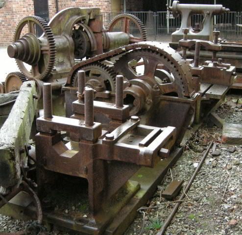
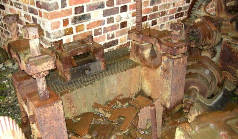
The old lathes at Martins comprised only a tee slotted bedplate, as a lathe bed, a sub table to hold the tools known as a piano rest, another deep rest for necking down, and as for the headstock it was only a set of gears in a frame, the mandrel driving the roll to be turned by a wobbler, As for holding the rolls during machining, this was the procedure (from 30 years of memory)
The end of the rolls were centred on a horizontal drill, and a "bomb proof" tailstock, was set up, In the mandrel was set a headstock centre, Tailstock ditto
The roll bearings were turned and then the tailstock removed and primitive housings were fitted to the bed for overall turning( the wobbler providing the drive), With the roll turning in its housing or steady thingys, great accuracy could be guaranteed as regards concentricity between the bearings and the main portion of the roll All of the toolwork was more or less a scraping process, and as regards the finish and accuracy only obtained by callipers!, it was amazing, A roll turner was a highly skilled craftsman

On the bigger rolls up until about 10 years ago in Coatbridge was the big roll foundry and machine shop of R.B. Tennant, capable of making a roll in excess of 100 tons Many of these rolls were in hard cast iron, In their Meadow works were very modern lathes by the german firm of Waldrich Seigen, real monsters, very powerful and precise machines more akin to a conventional lathe, Usual 4 jaw chuck and conventional tailstock, And for the finishing of the huge rolls for sheet and plate Etc. the finish was obtained by precision grinding In a plant of such modernity & magnitude, there was no place for callipers, and cluncking things with a hammer
Over at Clydesdale tube works, the pilger rolls were turned on big German Becker lathes, very powerfully being able to profile the offset weird roll formation in the hard steel used for these items This type of lathe used cams and hydraulics to the slides

Asquith mentions steam driven roll lathes these would no doubt be built by Messrs Thomas Perry & Sons of Bilston a very prominent maker of such items of plant.


Back
Top