Greg Menke
Diamond
- Joined
- Feb 22, 2004
- Location
- Baltimore, MD, USA
Some years ago I had the opportunity to use one of the big A frame screw presses at Tuckahoe (IIRC at least a 10ton model), fell in love with the action and finesse the machine afforded. Meanwhile I had one of the usual "12 ton" Northern tool hydraulic units (complete with warped table)- it works OK but I've never much liked it.
An opportunity came up to get a smaller press via this thread (Keystone Marine Motor Works (Essington, PA)) so I jumped at the opportunity, and eventually got it into the garage;
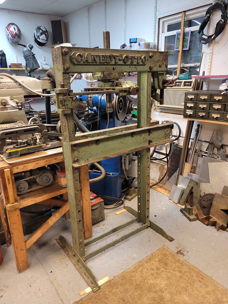
total weight is probably on the order of 600 lbs, an easy carry in a pickup;
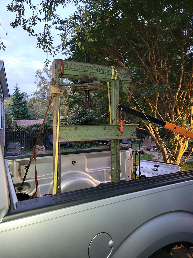
but the center-of-gravity is challenging if you can't pick it from high up on the frame. A shop crane is problematic, would be good to drop the table to the bottom and put shackles thru the pin holes as high up as possible. I picked using the table which made the lift really sketchy.
The screw head adds a lot of weight up high but its fairly heavy so not easily removed unless you have a suitable rafter or similar. The head is retained by the obvious pair of bolts, and is tightly fit between the frame's upper members (when reassembling, jack the upper frame apart slightly.
Inside the head I found a set of loose balls forming a thrust bearing to support the free motion of the ram. The smooth upper face is the thrust bearing which applies pressure to a workpiece.
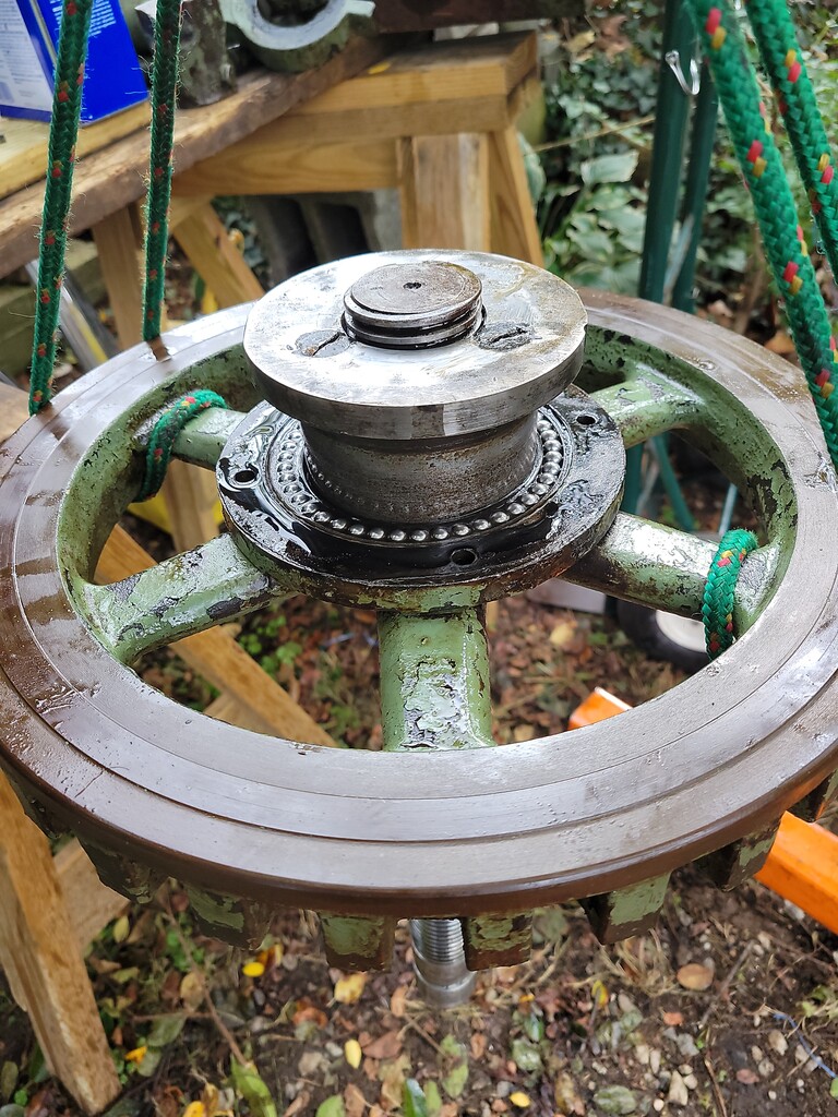
be sure to disassemble with a tray or cement mixing basin underneath, the balls go everywhere as soon as the head separates! The compounding lever system acts very cleanly up or down but is somewhat in the way when rotating the wheel by hand, perhaps something to get used to through use. I've not put floor anchors in for the other machines, I think I will need them for this machine once theres a length of pipe going into the compound lever knuckles...
The head is lubricated using a grease cup with screw-on cap to force lubricant into the screw and bearings, much like some old motors. The head was filled with mostly solidified circa 1920 grease.With oil as assembly lube the screw zips up and down very nicely. After reassembly I used #1 grease which worked well.
The arbor press tool is simple rack and pinion but it does have a lever and pawl, and a holding spring against the arbor rack teeth. I'm looking forward to broaching keyways on this, my cheapie hydraulic press worked but does not give a good feel for the cut.
A small assortment of possibly-OEM tooling came with the press; v-blocks, nice piece of plate to go on the table and some related bits which may end up being handy for the arbor press end of the machine. The machine does have an OEM v-head for the working end of the screw, its quite rough and will need some refinishing, but the set looks to be very handy for shaft straightening and similar.
An opportunity came up to get a smaller press via this thread (Keystone Marine Motor Works (Essington, PA)) so I jumped at the opportunity, and eventually got it into the garage;
total weight is probably on the order of 600 lbs, an easy carry in a pickup;
but the center-of-gravity is challenging if you can't pick it from high up on the frame. A shop crane is problematic, would be good to drop the table to the bottom and put shackles thru the pin holes as high up as possible. I picked using the table which made the lift really sketchy.
The screw head adds a lot of weight up high but its fairly heavy so not easily removed unless you have a suitable rafter or similar. The head is retained by the obvious pair of bolts, and is tightly fit between the frame's upper members (when reassembling, jack the upper frame apart slightly.
Inside the head I found a set of loose balls forming a thrust bearing to support the free motion of the ram. The smooth upper face is the thrust bearing which applies pressure to a workpiece.
be sure to disassemble with a tray or cement mixing basin underneath, the balls go everywhere as soon as the head separates! The compounding lever system acts very cleanly up or down but is somewhat in the way when rotating the wheel by hand, perhaps something to get used to through use. I've not put floor anchors in for the other machines, I think I will need them for this machine once theres a length of pipe going into the compound lever knuckles...
The head is lubricated using a grease cup with screw-on cap to force lubricant into the screw and bearings, much like some old motors. The head was filled with mostly solidified circa 1920 grease.With oil as assembly lube the screw zips up and down very nicely. After reassembly I used #1 grease which worked well.
The arbor press tool is simple rack and pinion but it does have a lever and pawl, and a holding spring against the arbor rack teeth. I'm looking forward to broaching keyways on this, my cheapie hydraulic press worked but does not give a good feel for the cut.
A small assortment of possibly-OEM tooling came with the press; v-blocks, nice piece of plate to go on the table and some related bits which may end up being handy for the arbor press end of the machine. The machine does have an OEM v-head for the working end of the screw, its quite rough and will need some refinishing, but the set looks to be very handy for shaft straightening and similar.
Last edited:


")


