What's new
What's new

Chatham Historic Dockyard: Sheds and their contents

Asquith

Diamond
Joined
Mar 3, 2005
Location
Somerset, UK
JD Chatham12.jpg1 JD Chatham13.jpg2 JD Chatham16.jpg3

Chatham Historic Dockyard, on the River Medway, east of London.

Kent Visitor Attractions, places to visit, Museums, Warships, Ropery, Submarine

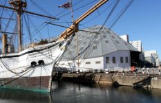
This remarkable wooden shipbuilding shed was constructed in 1838, allowing wooden warships to be built in the dry.

In 1904 the building slip was filled in and a mezzanine floor constructed for storage of ships' boats.

Now the shed is used to store all sorts of interesting stuff.

JD Chatham17.jpg4
Seen from outside, behind the sloop HMS Gannet, built at nearby Sheerness in 1878.
 
Last edited:
JD Chatham18.jpg5 JD Chatham19.jpg6
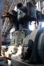
Large air compressor.

7
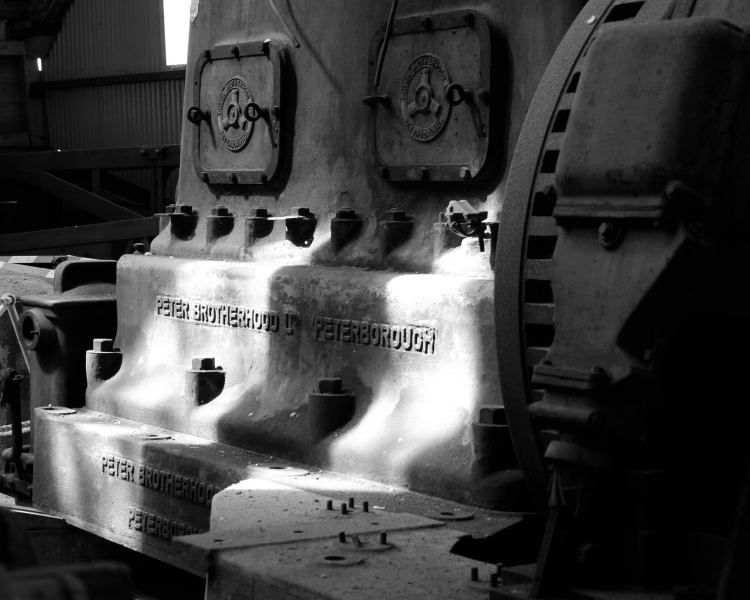
Peter Brotherhood are still going strong, although they have now been taken over by a US company.

Note the symbol on the crankcase doors, representing three cylinder radial engines (steam, air or hydraulic) which the company invented.

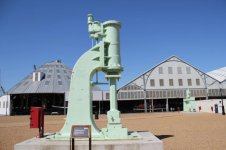
JD Chatham21.jpg8
Pick me hammer up, will ya, mate?
 
Last edited:
I suppose its no coincidence the the inside of the shed looks like an upside down boat ?. re the compressor we had a similar smaller one in Maidens, Hyde made locally in Altrncham, by Tilghman
 
Bodger,

The shed's design was purely functional, but it was built by shipwrights......

.....................................

More of the shed's contents:-

JD Chatham14.jpg9
Nearest hammer is by B & S Massey

JD Chatham24.jpg10
Lang lathe

JD Chatham15.jpg11
Darling & Sellers gear cutting machine

JD Chatham23.jpg12
Wm Muir planer
 
JD Chatham22.jpg13
This was made by Hulse of Salford, and I suspect that it's a punch of some sort.

JD Chatham26.jpg14
Cute little shop crane. No information.

JD Chatham25.jpg15
This diesel locomotive is much travelled. Made by Andrew Barclay in 1941. Gardner 6L3 diesel engine.

It invaded Normandy in 1944, and stayed on the Continent until 1946. It spent some time in the Middle East, and served at many UK ordnance factories and depots. It returned to France for the 50th anniversary of D-Day.

More here:-

The Dockyard Railway :: 0-4-0DM, AB357/1941 WD42, "OVERLORD"
 
The history of the diesel loco makes it sound like "the little engine that could" and I'm sure it still "can".
 
I used to live in Rochester, so Chatham dockyard was a favourite haunt. It used to be far larger, much of it having since been demolished. Just for the record, if any body is planning to visit the area, it is worth trying to fit in a visit to the Brook Pumping Station in Chatham, which although small, has a pair of nice oil engines, which used to be run regularly. They have a website: Old Brook Pumping Station
 
Asquith,
looking at the back of the Muir planer,is that one of a pair of bevels, suggesting screw drive? Also, does anyone recognise the model of the Lang lathe,similar in style to the one on e-bay a while back with no obvious model nos.
Richard
 
Xunil

Despite its diminished size. We managed to spend the whole day there. Even so, I now know we missed some things, including the former Marc Brunel-designed sawmill. We had a bit of a drive round the area afterwards, and only now, having read up about the place, do I realise that the nearby marina's basins were originally part of the naval dockyard.

Richard,

You are undoubtedly right about the planer having a leadscrew-driven table. Just inboard of the leadscrew’s bevel will be a multi-collar thrust bearing. A similar arrangement can be seen in the photos of this Whitworth planer:-

http://www.practicalmachinist.com/vb/antique-machinery-history/whitworth-planer-210742/

Unfortunately, I only took quick snapshots of the contents of this shed, and the photos aren’t very good. I will show some more, for what they’re worth.

JD Chatham27.jpg16

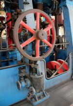
The next two show a steam turbine from a 'Blackwood' class frigate. I gather that these were a cheap and cheerful sort of vessel, although I suppose 'cheap' is a relative term in Admiralty speak.

The English Electric-designed turbines gave 15,000 HP going forwards, 5000 HP astern. That astern power would be useful when slowing and manoeuvring when dicing with submarines.

I think there were two turbines, driving into one gearbox. In the photos, the red valve atop the casing is to admit astern steam, the blue for ahead. There are several ahead valves in the 'blue' group, opening progressively to admit steam to individual groups of nozzles, this arrangement giving more economical cruising.

JD Chatham28.jpg17

All the astern power comes from just two rows of blades, seen on the left in photo #17. These exhaust into the condenser, which is immediately below the turbine casing.
 
JD Chatham29.jpg18

I don’t know anything about this triple expansion engine's origins. (Note: the frigate's gearbox is off to the right).

JD Chatham30.jpg19 JD Chatham32.jpg20 JD Chatham31.jpg21

The reversing gear might be of interest. It acts on what I assume is Stephensons' link motion. Note the hand crank, which rotates the spindle of the steam distribution valve.
 
If engines don't appeal, there's always the sheds. If I was to return to the museum, I'd spend more time looking at the former shipbuilding buildings.

Although the big wooden one is very impressive, its construction doesn’t represent cutting edge technology. In contrast, the neighbouring sheds do.

JD Chatham05.jpg22

In the photo above, the wooden shed is on the left, and the first of the iron sheds is on the right. Work started in 1847. The remarkable thing is that the iron framework is mostly cast iron. Fortunately it’s not an earthquake zone! However, damage did occur early on due to inadequate foundations in one area (ref 'Building the Steam Navy' by David Evans).

JD Chatham33.jpg23

Looking inside, we can see how much more lightweight and economical the iron structure would be, and how quick to erect, given the modular design. Even the I beam columns are castings.

JD Chatham41.jpg24 JD Chatham38.jpg25

More to follow.
 
Despite its diminished size. We managed to spend the whole day there. Even so, I now know we missed some things, including the former Marc Brunel-designed sawmill. We had a bit of a drive round the area afterwards, and only now, having read up about the place, do I realise that the nearby marina's basins were originally part of the naval dockyard.

The original dockyard was vast, most of it having now been re-developed. I was living there during the re-development, so I can remember how much has been lost. Interestingly, the No. 8 machine shop has survived; if you go to Google maps and enter 51.401785 , 0.536208 , the street view will show you the preserved framework. I believe the original plan was to use the framework for a new building. I can remember exploring this building when it was complete, although by that time the only machine left was a large grinder.
 
JD Chatham39.jpg25
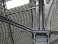
The arch castings are augmented by rolled iron (Tee?) sections.

JD Chatham40.jpg26

JD Chatham35.jpg27 JD Chatham36.jpg28

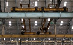
I was pleased to spot that the crane rails' beams were cast by Aveling & Porter in nearby Rochester. They became better known for steam rollers and traction engines. In fact they are reported to have made the first two steam rollers to be used in the USA (1868 and 1869, used at Central Park and Prospect Park - ref: 'A Hundred Years of Road Rollers' by Aveling-Barford, 1865.
 
JD Chatham34.jpg29 JD Chatham43.jpg30

Not all of the covered slips are accessible, including No. 7, completed in 1855. Now occupied by 'Turk's Boatyard'. It is said to be an early example of a covered slip incorporating overhead travelling cranes from the outset.

Most of the submarines built at Chatham were constructed here, including the Ocelot, which is preserved at Chatham.

This link has some interesting old photos, including photo #1 of a battleship, HMS Albermarle, which outgrew the shed:-

No.7 Covered Slip - Chatham Dockyard | Facebook

There’s an interesting photo of a roof structure in Building the Steam Navy (Fig 46) which is said to be at Chatham, having been resited from Woolwich Dockyard, where it was their No. 4 slip. This shows a very lightweight construction of the main roof, making extensive use of wrought iron bars of slender section arranged in clusters of four bars separated by iron spacers. I don’t know what the name for this construction is, but photo #31 should give an idea. My photo shows No. 7 slip, but I can’t reconcile it with the photo in the book.
Shed 7.jpg31
 
Great buildings..... how did they survive the war? did they camouflage them so they didn't get bombed or did the Germans just do terror bombing of London and not try to take out industries? You would think it would hard to miss something this size and they certainly should have known about them.

Thanks for sharing these and all you do.
 
Asquith,
looking at the back of the Muir planer,is that one of a pair of bevels, suggesting screw drive? Also, does anyone recognise the model of the Lang lathe,similar in style to the one on e-bay a while back with no obvious model nos.
Richard

Hello Ruston,
I have seen a few of this pattern of Lang's up in this neck of the woods, I have never also been able to ascertain if any model number ever existed for this pattern, as a design of lathe it was shown in the Associated Machine Tool catalogue for the mid 1920 period It was explained as single speed drive, sliding gear, 12 speed headstock pattern, This design of lathe in the conventional sliding surfacing & screwcutting lathe pattern were produced in sizes from 6&1/2" centre height up to18&1/2" centre height
Also they were sliding bed lathes of this type from 12 &!/2" centre height up to18&1/2"centre height over the bed with a gap depth on the largest I believe, to take up to a 48" dia work piece

Also some quite large boring & facing Langs with this unique headstock were to be found in the Clyde area, I have seen one with a four paw chuck/faceplate capable of handling an eight foot dia work piece approx. I believe they might have made this pattern of lathe alongside the well known bullet head pattern of machine, ( bullet heads were still being made in the late 1950/s) into the 1930 era?
 
JD Chatham44.jpg32
One of covered slips houses a collection of lifeboats. Lifeboats in Britain and Ireland are operated by a charity, the RNLI (Royal National Lifeboat Institution).

JD Chatham45.jpg33
1933 petrol (gasoline) engine for a lifeboat, made by Weyburn Engineering Co. Designed by the RNLI to be waterproof, provided the air inlets kept their heads above water.

JD Chatham46.jpg34
Also waterproof (up to a depth of 7 ft) is this Fowler tractor. Used for lifeboat launch and recovery.


Back
Top