What's new
What's new

Colchester Cross Slide Screw Nut Adjust.?

Can'tWeld

Aluminum
Joined
Nov 2, 2013
Location
Humble,Tx
Guys I have look at this cross slide screw nut and can't figure it out.I was told that its to remove the slack or plan in the screw but how do you get to it to adjust?In the manual that I got from Tony in UK it shows that where you see the small hole that a screw should be there to adjust the wedge up/down but the hole is not threaded or goes all the way through.Is this one of those manufactor defects???
Colchester 13' Roundhead M#53656
 

Attachments

  • DSC02867.jpg
    DSC02867.jpg
    92.3 KB · Views: 6,898
The adjustment is provided by bolting (fastening) the larger bronze nut segment to the cross slide and pushing the steel wedge segment down between it and the smaller segment with a screw threaded in the cross slide. It is a common method used on many machines.
 
The above post basically describes the method of operation. I'm not a big fan of the idea. It's a bit of a flawed concept really. If your screw is worn towards the middle as most used machines screws are, and you thighten up the nuts you can't easily wind to the extremities of the screw.

Regards Tyrone.
 
Guys here's another pic from the side,but there is no adjustment screw not even in the top of the cross slide,no hole to get to a screw.In the manual that I got from Tony,it shows a adjustment screw but it don's show how to get to it.But this setup does not have an adjustment screw.
 

Attachments

  • DSC02875.jpg
    DSC02875.jpg
    94.3 KB · Views: 4,491
A photo of the cross slide top would be more help than a photo of the screw and nut. If my memory is still functioning you should have a counter bored drilled hole for a nut fixing screw, a small tapped hole for the adjusting screw for the wedge and an elongated counter bored and drilled slot for the other nut fixing screw.

If you don't have these holes for some strange reason, you'll have to create them.

Regards Tyrone.
 
Tyrone,judging from what I have found since I started this restoration I would say that its a good probability that its not original to the lathe if we'll talking about the screw nut.It was in good shape but the top slide nut was not so I replace it.Strange!But that brings me to the top slide itself,there is no access to a adjustment screw for the compound slide nut.Oh well,this is a mystery just was wondering.Thanks for suggestions
 
Here's a pic from a manual that is close to my lathe.It shows the opening to access the adjustment screw but my cross slide does not have these openings but it does have the nut that can be adjusted to remove the slack.
 

Attachments

  • DSC02892.jpg
    DSC02892.jpg
    89.6 KB · Views: 7,992
Don't forget that the adjuster is for taking out wear on the nut, not the screw, so you have to set the thing up the end on the unworn part of the screw. As Tyrone says doing it in the middle on the worn part of the screw will jam things up. Sorting things out after Harry the Hamfisted has jammed things up can be a truely miserable experience. The nut tightens up and expands just fine. Getting it to go back if the adjustment has been overdone isn't so easy! Not something to be done on an in-service machine when you have five spare minutes before the Friday afternoon hooter. Should only be done as part of a proper strip and clean service or, as in your case, full go through and restoration.

As to fitting I think your lathe is too old to have been originally fitted with an adjustable feed nut. Two types were used. You have the early version with the same single bolt fixing drilled for an oil hole as the fixed nut used. The adjusting screw is inline with the feedscrew and the moving part of the nut freely floating. The later version is as Tyrone described with two hex socket cap screws in a diagonal line holding it to the slide with the adjuster in the middle. One holding screw goes through a plain hole into the fixed part of the nut. The other goes through a slot into the moving part. The moving part is still smaller than the fixed part but the disparity in size is not as great as it is for yours. As I understand it the adjustable nut appeared around the same time as the interim "Mk 1 1/2" lathes combining the later "safety" apron with the old round topped headstock. The later type appeared some time in the production of the Mk2 flat topped headstock machines and was retained when the whole range was remodelled into the square styles Student 1800, Triumph 2000 et al.

I imagine Colchester long ago decided not to supply spare fixed nuts as the early type adjustable is a direct replacement for the fixed version. Lathes needing spare parts can be assumed to have some wear so adjustment might be desirable. As ever its important to ensure that a single bolt fixing feed nut actually is dead inline with the feed screw. I've met folk who found this too difficult. You will almost certainly need to add an adjustment screw to your slide. Its unlikely that the natural position of the wedge corresponds with the neutral position of the two portions so that the thread is effectively continuous. The nuts may also have been made with a slightly thinner than specification male thread to give a full range of adjustment starting, as it should, slightly below "zero". Even if all is correct in alignment and spacing its probably not a good idea to have the adjuster wedge floating.

Clive
 
Can’t Weld
I have a c. 1967 12” swing Colchester Dominion and it only had a fixed nut on the cross slide with no provision for the adjusting set screw as shown in post #7
I have chased the thread on the cross feed screw a few thou. smaller to remove the wear and made a new non-adjustable nut to fit the chased thread .
Regards,
Jim
 
Nooging through what Colchester data I have to hand the question of what goes with which got a whole lot less clear. I always thought the adjustable nut came in with the telescopic cross slide feedscrew allowing the taper turning attachment design to be upgraded from the old fixed slider bracket system which required the feed nut had to be disconnected from the cross slide to use pretty much ruling out an adjustable nut. The later, telescopic screw, version works via the feedscrew so clearly its important to minimise play in the screw and nut. However the data I have shows a fixed nut for both types although the installation instructions for the later taper turner retrofit kit refer to fitting the new nut supplied. But no mention of adding an adjuster access hole as would be needed if the new one were of the adjustable type like yours.

Anyway it would probably be prudent to investigate re-engineering that adjustable feednut so that both halves are positively fixed to the slide. One assumes that Colchester had good reason for changing the design to the style described by Tyrone. If nothing else fixing the moving part via a bolt or screw in a slot gives you a chance of moving things positively in both directions. The original seems engineered upside down to me. Inverting it with a stud'n nut to pull it up and spring round the stud to push it back down seems better than a simple push screw sort of holding it down.

If you have the old type taper turning attachment it becomes impractical to remove the feednut if it has more than one bolt holding it. Obvious work around is to remove the nut holding the handle and dial assembly so the screw can slide freely back and forth. Thats the way my Smart & Brown is arranged and it works well. To me the complex double dovetail slider and telescopic feedscrew systems are just adding complexity and reducing rigidity to solve a non problem. Maybe all that extra weight on the backside of the saddle partially compensates for the apron weight evening out bed wear.

Clive
 
I recently pulled a colchester cross slide apart (scrap yard find) to take a look at the nut for interest. Its similar to the one you show except the wedge is a little different. The operation appears the same. The main nut body was held to the slide by a cap head threaded into the nut body. Next to this was a small threaded hole in the cross slide with a set screw which pushed the wedge into the assembly. Not much help Im sorry. Mat
 
+1 - me too!

I have a 1965 Colchester Triumph mk1.5 (15x48) with the taper attachment. The cross slide has had about 20 thou of backlash ever since I acquired it six years ago. I had assumed I'd have to make a new cross nut for it, but after seeing this thread decided to tear it apart and hope I got lucky.

I did! It's the same adjustable nut from the original post, and like the original poster, did not have anywhere in the cross slide to install a screw to press on the wedge to utilize the adjustment. I don't know if this nut was original to the machine or not, but I do know for sure that I'm only the 2nd owner - Clausing still had the bill of sale from when Florida Power & Light bought the machine new - and I got it from them.

The hole in the wedge isn't tapped, but looks like a good fit for a 1/4" SHCS to press down on it, so I guess that's what I'm going to tap the cross slide for - but it'll have to sit recessed so it'll have to be just the right length, or recess the hole a bit extra, I suppose.

Here's a pic: https://lh3.googleusercontent.com/utgtkZkyBBOy2pqYBWV88ePLX1DNAVvgYxhoH0mGIA_Z2pRp33u45QpmKY1-wnKzPl2AN78huoicZgADuZWTpuNOw_Xl1cbtL64Pavf-qB5H93gBIeVyV_Yxd3B9BLgy9GjkHI6wEmsWCSFcACfMJaG3B36yGxO3pwv2xeyWmNoHGSyQGM4lYJ657lmfvFhdJ0WAoycox3bfThcmjQflIo8I0HBy-gKUNSmUflz12cXEVEst0B2xtz-COYrlmOZ3xyMBXE08izxjpcZMWQih1jDfnvHHhAqj-k40Es3MVTy93MiyjP9zhRwUPZjCE9GYrna0WU_y75NBz4f__-AFgbXVlN49cVSbYEkHjmhLXe7-0eKRmrT04b_8oNfNFbccZNVjUfiYE5TYaiDXmzCkHe5d6FSkwOLVr3frVIImxgyaBdnGw4bIGVmgFtMmlsxxJqdkyusu6NN3AoA0tDGFRA5IO2sySD-rDxE-agrWyjqG3MeGRsd3iY8ZGeHzL65Jx7obxtHGcU7M-JAslrJNH3a6WC3t7uYmDB2OauT4XEkx97fjba53jNVOy-FNTAkomlny1v5mTvJlh938UFm4eN9Lvex4uyTFaslWjdxY=w353-h265-no
 
Tapping the hole for the screw to press on the wedge and then reassembling everything got rid of 1/2 of my backlash, I'm down to 10 thou now. That's better, but still leaves a bit to be desired.

IMG_20180709_180526 (Large).jpg

It got me wondering if I'm missing something in my setup. I didn't realize until disassembling it that the taper attachment is always part of the cross slide's movement, even when you're not using it. I'm wondering now that I have the play taken out of the screw/nut combination if the rest of the slop is in the taper attachment. Is there something I'm supposed to be doing to lock the taper attachment when not in use? It's just hanging there, such that pushing or pulling the taper attachment by hand does move the cross slide, and I'm wondering if that could be contributing slop. Should that be locked down somehow when not in use?

BTW if anyone needs to add the hole to their cross slide, I drilled and tapped the 1/4-20 hole 0.8185 back from the center of the bolt that holds the nut to the slide. I'm not sure if it was exactly right, but the 1/4" bolt did enter into the hole in the wedge just fine.
 
Hi Jason,

There are two thrust bearings at the rear of the cross slide screw, then there is a nut on the end. You might be able to take the slack out of it by tightening that nut. Begin by tightening it to the point that it begins to get just a little harder to turn the screw, then back it off, just enough so that it turns easily again.

Brian
 
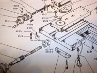
Jason, great point about slop from the taper attachment, in fact in some designs it starts at the lowest casting. The Nardini TA is a case in point, the bottom casting in the pile, post #4 PN 969, is bolted to the rear of the saddle (https://www.practicalmachinist.com/...rdini-taper-attachment-please-explain-159707/).
Being bolted direct to the saddle it is absolutely rigid, all good so far. Now we come up to PN 964, the longitudinal slide, is a source of movement in the slide between it and 969, there has to be adjustable clearance for it to slide.
Now we come up to PN 963 which should be rigid being bolted to PN 964, but it's slop is between it and the angled follower (My terms) PN 956 which has to have clearance to slide on it. Then on up to PN 957, the anchor for the screw's thrust bearings. From that point on all is well, but you can put a dial indicator on the slide of a Nardini and pull it towards and away from you and watch the needle dance!
Plus either you let that situation exist or tighten all the gibs until you need to use the attachment.

On mine (2 so far) I altered the design, and whether or not other telescopic attachments can be also altered is outside my knowledge.
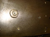
PN 957 slides perpendicular to the bed inside PN 950, which is bolted and taper pinned to the saddle. The angled follower 957 has just enough room in it's corners looking down on it to drill/tap a couple 1/4-20 or 6 MM screws, these screws are flat headed type socket screws set catty cornered into that bearing block top, through the top of 950 which is countersunk for the screws. Between the bottom of 950 and the top of 957 I counterbored recesses for 1/2" OD washers, these washers were carefully surface ground to just take up the space between the two, and cannot get free because of the counterbore.

On top of 950 by the screws I stamped "Remove screws to use TA".

This effectively bypassed all the slop producing areas making a very rigid cross slide anchor out of it, in fact, you could take the TA off leaving PN 950 on holding the back of the bearing block and it would work nicely. Yet, as described you can take the two flat head screws out and setup your TA and use it too. Those two washers have to be bur free, but a bit of polish on the edges of them would help when used as a taper attachment.


Back
Top