JHOLLAND1
Titanium
- Joined
- Oct 8, 2005
- Location
- western washington state
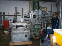
dropped in on one man scientific shop--dedicated owner
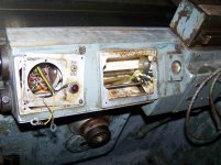
purchased 3 inch DeVlieg jigmill from Watervliet Arsenal
and is tearing down the table with impressively complex sub-systems for
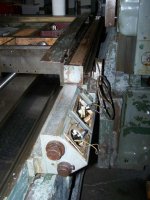
positioning and limit stop accuracy
build year of this unit 1962
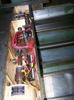
incorporates resolvers for positioning repeatability which company states is 0.0001"
resolvers are covered with poly-ribbon which minimises swarf entry
special comment--table mechanism centerpiece is fixed lead screw and spline shaft worm and gear construct which allows part positioning under no load--
cutting forces are applied by moveable leadscrews on x, y and spindle z axes
table is locked down during material removal
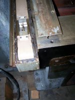
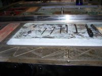
a few shots of table with platten removed
purchased 3 inch DeVlieg jigmill from Watervliet Arsenal
and is tearing down the table with impressively complex sub-systems for
positioning and limit stop accuracy
build year of this unit 1962
incorporates resolvers for positioning repeatability which company states is 0.0001"
resolvers are covered with poly-ribbon which minimises swarf entry
special comment--table mechanism centerpiece is fixed lead screw and spline shaft worm and gear construct which allows part positioning under no load--
cutting forces are applied by moveable leadscrews on x, y and spindle z axes
table is locked down during material removal
a few shots of table with platten removed


")
