What's new
What's new

DoAll 1612-3 Top Wheel Removal - how?

Joined
Jun 13, 2019
I'm trying to clean up an old 1612-3 saw and want to remove the top wheel. Does anyone know how it comes off? I can rotate the top on top only a couple of turns then it becomes extremely tight. A wrench can turn it a little further but it still tightens up and I don't want to break anything forcing it.

There were two knobs on the shaft. The outside knob was a pressure fit to the shaft with a spring pin driven into the face at the joint where the wheel met the shaft. I've removed the pin and outside wheel. The inside wheel appears to be locked to the shaft but that's the one that I can't figure out how to get off.
 
The slightly smaller outside hand wheel is the tilt adjustment used to center the blade tracking on the wheel. The slightly larger hand wheel is a simple lock nut that runs on the same thread of the outer hand wheel. Once the inner hand wheel is loosened, the outer smaller hand wheel simply unscrews taking both hand wheels off at the same time. After that you will find a locking washer with a bent tab. That must be straightened allowing the tabbed nut to unscrew. The band wheel simply pulls off the shaft. You will find a spacer behind the wheel hinge. Once the hand wheels are removed that spacer will be loose. Don't lose it! It will fall out when the wheel is tilted on the hinge.

If you continue to disassemble, be careful as the hinge casting is pinned with long 1/4" dowels to the saw frame. Once the screws are removed, the casting must be pulled off straight or you will shear a pin. (Ask me how I know). Removing the pin was a mistake. Put it back.
 
Last edited:
The slightly smaller outside hand wheel is the tilt adjustment used to center the blade tracking on the wheel. The slightly larger hand wheel is a simple lock nut that runs on the same thread of the outer hand wheel. Once the inner hand wheel is loosened, the outer smaller hand wheel simply unscrews taking both hand wheels off at the same time. After that you will find a locking washer with a bent tab. That must be straightened allowing the tabbed nut to unscrew. The band wheel simply pulls off the shaft. You will find a spacer behind the wheel hinge. Once the hand wheels are removed that spacer will be loose. Don't loose it! It will fall out when the wheel is tilted on the hinge.

If you continue to disassemble, be careful as the hinge casting is pinned with long 1/4" dowels to the saw frame. Once the screws are removed, the casting must be pulled off straight or you will shear a pin. (Ask me how I know). Removing the pin was a mistake. Put it back.

I think this is very helpful. Right now the inner hand wheel is locked solid to the shaft. Do I understand correctly that I need to get that to loosen on the shaft, or is the shaft supposed to turn with the inner wheel? I think from what you’re describing the outer wheel should be locked to the shaft via that pin and the inner wheel should be able to be tightened or loosened to allow adjustment.
 
As I understand it, you have removed the outer hand wheel by removing the pin. That is wrong. The threaded rod and the outer hand wheel is attached to is the tilt adjustment for the band wheel. The inner hand wheel is only a lock nut so that the outer hand wheel and rod does not turn inadvertently. If the inner hand wheel is tight, turn that hand wheel counter clockwise loosening the threaded shaft. Now just turn the outer hand wheel counter clockwise unscrewing and removing both hand wheels and threaded shaft together.
 
I think you are over complicating this assembly. The parts drawing is very unclear, so I can understand your confusion. It is however, very simple.

Thanks to your help I finally got it off. I agree that it looks like it should be simple, but I've found that almost none of the stuff I'm involved in is ever simple.:crazy:

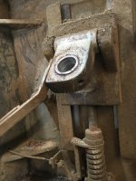
In this case the small threaded shaft that the locking know should thread onto is apparently seized to the knob. Attempting to unscrew the knob would turn the entire shaft and somehow that's apparently attached to a much larger threaded shaft that screws into the hinged part of the wheel mechanism. The reason it was stopped after two turns or so was because there was a setscrew through the hinge tightened onto the threads of this larger shaft.

IMG_4069.jpg

Also, you're absolutely correct about the drawings. I couldn't make heads nor tails of them.
 
I think you are over complicating this assembly. The parts drawing is very unclear, so I can understand your confusion. It is however, very simple.

Thanks for your help, Steve. I finally got it off. Turns out there was a set screw through the side of the hinge tightened down on the threads and that was apparently why it wouldn't make more than two turns or so.
 
After taking things apart to see what I had I was able to find a diagram online that shows the setup for my saw. If you look at the top right of this diagram (DoALL Sawing DoALL Sawing) for assembly 22237, that seems to be what mine looks like.

Parts 2, 10, and 15 are still locked together solid. I've tried locking part 10 in a vise and using a blow torch on the wheel (part 15) while using canned air on the small shaft (part 2) and a pipe wrench on the wheel and it won't budge. I'm thinking I may need to remake both of those shafts.

Parts 7, 8, and 9 are supposed to be a set screw, lock nut, and insert. I assume the insert is a soft metal so as not to tear up the threads on part 10. Unfortunately that was long gone on my saw and the set screw was locked right into the threads so they're somewhat tore up from that.

Lastly, it shows parts 5 and 6 being spacers and neither of those pieces appear to be present on my saw. Does anyone know what the purpose of having three spacers there would be since apparently this saw had been running without them?
 
First, it normally is not necessary to remove the item 10 from the hinge to remove the saw blade wheel. The fact that you did without loosening the set screw caused the axle thread damage. I assume you have now removed the blade wheel from the axle, is that so? The spacers 5/6 are to provide a thrust surface for the bearing inner race and to space the band wheel away from the hinge. There is some available space on the axle to move the band wheel latterly for correct saw blade tracking on to the center of the tire. Remember the top wheel must be in general alignment with the saw blade guides.

I cannot tell what the problem is with parts 2, 10 and 15 from here, but I can say that the threaded shaft, part 2, has no chance of turning in part 10, the axle, without the hand wheel, part 15, being loose first. I think those parts are still available from DoAll. If not, DoAll will send you the drawings of those parts so you can make them yourself, if you ask them nicely.
 
First, it normally is not necessary to remove the item 10 from the hinge to remove the saw blade wheel. The fact that you did without loosening the set screw caused the axle thread damage. I assume you have now removed the blade wheel from the axle, is that so? The spacers 5/6 are to provide a thrust surface for the bearing inner race and to space the band wheel away from the hinge. There is some available space on the axle to move the band wheel latterly for correct saw blade tracking on to the center of the tire. Remember the top wheel must be in general alignment with the saw blade guides.

I cannot tell what the problem is with parts 2, 10 and 15 from here, but I can say that the threaded shaft, part 2, has no chance of turning in part 10, the axle, without the hand wheel, part 15, being loose first.

It was never my intention to remove item 10 until it started to come out on its own. When I attempted to loosen the hand wheel (part 15) the entire assembly (2, 10, and 15) unscrewed as a single piece damaging the thread on part 10 in the process. Obviously when you start putting torque on the hand wheel it's going to unthread the weakest connection first and apparently the threads on part 10, while being locked down with a set screw, were weaker than the threads holding the wheel to the threaded shaft (part 2). Fortunately I think I caught it before too many threads were mangled and I'm pretty sure I can easily clean them up with a thread file.

I was able to remove the wheel from the hub once I got the above items removed.

I finally was able to get the assembly apart by chucking it up in the lathe and drilling out part 2. Once it was almost completely drilled out I was able to unscrew the hand wheel and then the threaded shaft itself. It looks like it'll be a lot easier to replicate the shaft as opposed to the axle and/or hand wheel so my priority was on preserving those two as much as possible. I have no idea how the hand wheel was so thoroughly locked to the threaded shaft that it wouldn't loosen even with the whole torch/giant wrench mentioned above.

Since the spacers were missing, any clue as to what size I should start with to get things close? I assume fine adjustment may be needed once it's time for reassembly.
 
Last edited:
You won't really know the size of the spacer until assembly time and it will be a balance between spacer part 4 and spacer part 6, but as a guess an 1/8" would be a start at least. Every machine is a bit different as the saw frame is a weldment. Please also note that the axle itself is part of the adjustment, as it can be screwed in or out a bit from the hinge giving you more axle room to space the top wheel into alignment with the blade guides. You won't know until you reassemble the saw. As you can also imagine, as part 2 is actually two pieces, the second piece is also just a spacer that also may need to be a different length to achieve the correct wheel tilt.


Back
Top