What's new
What's new

E. E. Baugh Steam Plant.

Lester Bowman

Hot Rolled
Joined
Apr 9, 2011
Location
Modesto california USA
These picture's are of a small steam plant with some connection to E.E. Baugh Mount Holly, New Jersey. The reason I say connection is because the Township itself is much later than the mechanical design of the engine. Also the threads and fittings are not American threads seemingly Whitworth but I haven't gotten far enough along to really tell.

This engine is made of either " Red Brass " or Bronze. I'm leaning toward Bronze based on the Patina.It is a very small engine with a 6" flywheel with maybe a 3/4" Bore. Beautiful little thing. A puff of air from my lungs will keep it going quite awhile !

I don't believe it is a toy. It is made far to well to be a boy's plaything. The design of the engine places it into the late 19th Century. Now the little plunger pump does appear to be from some engine sold commercially probably from Germany. It doesn't approach the same workmanship which appears in the engine and boiler. Note the connecting rod on the engine with Gib and Cotter. The cylinder head screws have been replaced somewhere along the line.

I love the FORM of the Box Bed and the golden Patina. Every surface has been beautifully finished..all the casting marks removed. The Box Bed has no section thicker than 1/8" with most of it being 1/16" thick. Beautiful little thing.
 

Attachments

  • 100_5131.jpg
    100_5131.jpg
    83.7 KB · Views: 293
  • 100_5135.jpg
    100_5135.jpg
    88.2 KB · Views: 297
  • 100_5134.jpg
    100_5134.jpg
    87.2 KB · Views: 260
  • 100_5132.jpg
    100_5132.jpg
    63.5 KB · Views: 260
  • 100_5141.jpg
    100_5141.jpg
    72.7 KB · Views: 261
The pressure gauge is unusual surprising me with its mechanism. Internally it is all mechanical its mechanism being activated by a pressure operated plunger or diaphragm assembly which threads into the Gauge case.

The Gauge Face is Zinc. The gauge is unmarked. Last pic shows how it attaches to the steam manifold which contains the remnants of a weighted Safety Valve. I replaced the crudely cut window glass Crystal with one for an old pocket watch.

Has anyone seen this design before ?
 

Attachments

  • 100_5125.jpg
    100_5125.jpg
    93.3 KB · Views: 170
  • 100_5126.jpg
    100_5126.jpg
    86.2 KB · Views: 166
  • 100_5127.jpg
    100_5127.jpg
    72.2 KB · Views: 164
  • 100_5129.jpg
    100_5129.jpg
    82.3 KB · Views: 168
  • 100_5143.jpg
    100_5143.jpg
    63.8 KB · Views: 151
Last pics are of the boiler. It is 5 1/2" in diameter with beautiful riveted construction. Outer shell is Brass, internal formed parts Copper. It sits on a base made from an old iron cased pressure gauge with a small round Gas burner. The burner is made in the USA..should have taken a pic of it.

The water column threads have been "pulled" in this boiler so the original water gauge ( which I have) is unusable. Reason I think it may be Whitworth it the threads on the original water gauge are straight threads, no taper. I can easily re-thread these "pulled threads" with a 1/8" NPT Tap. Fortunately the rest of it is in perfect condition.

I have never seen a boiler so beautifully constructed. It is made exactly like a full size riveted boiler excepting the outer rivet heads have been filed flush. These rivets have been carefully fitted into "counter sink's" which you can clearly see in the photo's.

One of the pics show the Smoke Box and stack and various parts. Little by little each part is being repaired and reinstalled. This steam plant is a true mystery. If it is an American made engine..why the odd threads ? Where did these beautifully made engine castings come from ? Why is the base and burner so much different from the rest of the plant ? So many questions ! :)
 

Attachments

  • 100_5137.jpg
    100_5137.jpg
    64.9 KB · Views: 183
  • 100_5138.jpg
    100_5138.jpg
    83.6 KB · Views: 166
  • 100_5139.jpg
    100_5139.jpg
    102.5 KB · Views: 174
  • 100_5140.jpg
    100_5140.jpg
    102.5 KB · Views: 158
  • 100_5142.jpg
    100_5142.jpg
    94.3 KB · Views: 166
The steam gauge design goes to some early designs by Ashcroft - perhaps pre-civil war - which afterwards were obsoleted by the generalized adoption of the Bordon tube type.

This is covered in "Antique American Steam Gauges" by David.

"Counter sink" boiler rivets were used and I would guess up into the 1870s if not a bit more. The original "Baxter Colt" stationary self contained boiler/engine was built almost exclusively this way. Colt-Baxter production began in 1867ish and ended in the early 1880s as cheaper engine producers (and boiler constructors) became more common.

Whitworth threads were common through the American Civil War. Americans really didn't have a big urge to develop home grown tooling since most tooling was based on tool steel - and the primary producers of tool steels were English glass-blowers - at least until the Civil war. I myself have a woodworking lathe which is a no-name lathe, made in the style common in Worcester, MA until at least the 1880s, and probably pre-dates the Civil War. I think it is a Shepard-Lathe & Co. A later Lathe & Morse lathe which is documented online is nearly identical. My lathe is notable in having headstock bearing cap bolts done in 7/16-14 BSW, which to a casual use SHOULD fit 7/16-14 UNC - but they don't. One gets the bolts screwed in about 6 turns and it "binds up" on the 55 degree included thread angle. But this is a lathe likely made before the Civil War.

Lathe & Morse Tool Co. - Photo Index | VintageMachinery.org

8310-A.jpg


Joe in NH
 
That thing really does look very well made and is quite "pretty". Seems too small for practical use, might it be some sort of sample piece or the like?
 
JST...the same thing crossed my mind. It is very difficult without some sense of scale to have a realization of its size. It has a 6" diameter flywheel but one could easily jump to the conclusion its a much bigger engine. What is so amazing is its likeness to full size.

Thank you reggie for the Mount Holly connection. One could almost assume a connection here and the time frame overlaps. It is a mysterious little thing. The threads throw me. How could such a LATE engine ( assuming the nameplate is correct ) be such an aberration from engines built in that time period? Even Model engineer's were using standard threads at the time or the "ME" threads which originated in England.

So what is it? What does it represent? Perhaps " E E Baugh " is the son and put together his Father's handiwork as a memory. Perhaps EE and EA Baugh is the same person.

It is also very possible these pieces were purchased and assembled by E.E.Baugh sort of like some do today, putting together a working steam plant for their own pleasure. These pieces could have been very old at the time. They may have earlier roots than the Baugh connection. The different levels of workmanship add intrigue to its genesis.

Salesman Sample is a term bantered around way to much when it comes to small steam engines. This engine has no distinguishing features beyond what was common in that time period. But man..this little thing looks exactly like its bigger brothers and could very well have been carried in a suitcase or traveling trunk.

Also see how the flywheel rim is made. It is a very early style with narrow rim. I simply love the engineering and beauty this engine has in its details. Combine all this with the early style pressure gauge and it makes one wonder. So little is known about these early steam engines. Technology was certainly an infant in regards to photo's and records. I wish there was more and I wish the information wasn't so hard to find.
 
A few pleasant hours of shop time has resulted in getting this small steam plant back to operating condition.Well..more than a few but pleasant nevertheless :)

Most of the piping was missing. The little plunger pump came with the engine but had no check valves.I straightened that out and put in a bypass. After testing the boiler I made a fancy clamp to secure it to the firebox. I made an adapter with orifice for the burner. I fitted a different safety valve..a bit large but it'll work. I couldn't save the original safety valve, it was too far gone.

I always try and use as many original bits and piece's as possible. On this one I very sympathetically cleaned the engine and boiler. In fact I didn't clean the engine at all opting for a rub down with light oil. I made a displacement lubricator from a small brass oil cup and corrected the problem's which always seem to come with these antique steam plants.

I think I'll fit a band around the smoke box top cap to make it look pretty. I'll fire it up this afternoon or tomorrow and enjoy the beauty of a beautifully made steam plant complete with the smell of steam oil.
 

Attachments

  • 100_5145.jpg
    100_5145.jpg
    70 KB · Views: 153
  • 100_5146.jpg
    100_5146.jpg
    85.3 KB · Views: 147
  • 100_5148.jpg
    100_5148.jpg
    67.9 KB · Views: 169
  • 100_5150.jpg
    100_5150.jpg
    69.4 KB · Views: 152
  • 100_5151.jpg
    100_5151.jpg
    77.8 KB · Views: 135
These are the last pic's some taken before the mechanical restoration. I REALLY like this small pressure gauge fitted to this mysterious plant. It is a low pressure gauge so this plant will run on very low pressure. The engine is incredibly well made. I can keep it rotating constantly under lung pressure only so I'm quite sure it'll run and pump its own water feed quite happily.

It is not what I consider to be a working " power focused " steam plant but rather a demonstration piece built for educational purposes. I don't believe it is a boy's toy or something bought in a model shop. The exquisite workmanship and design of both engine and boiler suggests something different than an expensive toy. What I do not know. What I do know is the way it was originally piped up was done by someone else because the threads are regular 1/4" x 40 tpi Model Engineer Pipe threads. The threads on the engine and boiler are different than any Standard USA Thread.

One thing I will be changing are the straight test cocks which have no "turn down" on them but discharge directly into ones face ! I'll keep the originals in place but fit some small copper pipe's too send their discharge "down" rather than "out". I'm still considering exactly how to do it. Also I'll fit some small wooden handle's over their operating lever's to prevent burnt finger's and give them a nicer look.
 

Attachments

  • 100_5147.jpg
    100_5147.jpg
    67.2 KB · Views: 94
  • 100_5144.jpg
    100_5144.jpg
    68 KB · Views: 128
  • 100_5128.jpg
    100_5128.jpg
    74.7 KB · Views: 81
  • 100_5130.jpg
    100_5130.jpg
    79.8 KB · Views: 98
  • 100_5133.jpg
    100_5133.jpg
    91.9 KB · Views: 80
Lester:

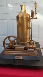
You do have a knack for finding (and showing us) some of the most interesting and well made model and small-sized steam plants. My guess is Mr. Baugh built the steam engine as a working model. It was a common thing many years ago for machinists and stationary engineers as well as marine engineers to build model steam engines. An old friend had a model of a steam launch in the window of his auto parts shop in Marquette, Michigan in the 1970's. The launch was about 3 feet long with a working steam plant. It had a single cylinder vertical engine, all made of bronze castings, with a mainframe in keeping with what was in use on the Great Lakes many years ago. It also had a vertical boiler, fully jacketed. I used to enjoy looking at that model, and I was told it had been made by a stationary engineer in the waterworks in Duluth, MN many years earlier. The founder of the auto parts store had come from Duluth, and apparently, the stationary engineer at the waterworks was a friend who passed his model along to him. Same sort of construction, one-off bronze castings, one-off fittings apparently made by the same man who made the rest of the model.

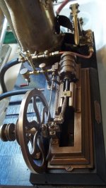
Mr. Baugh may well have been any of several professions, as many years ago stationary and marine engineers were usually fairly accomplished machinists. Mr. Baugh likely made patterns and had them poured in bronze in some local foundry. Making the pattern for the cylinder with cored steam passages was quite an accomplishment in its own right, given the small size of things. Mr. Baugh was following stationary engine practice of the 1860's -1890's, I think. The engine is too nicely made and too well finished to have been used as a "working engine" for something like driving sewing machines (a common use for small "working" steam engines and boilers).

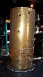
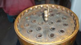
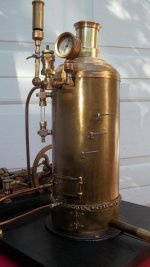
The boiler is a fine piece of work in its own right, and has a "wet" or "submerged" firebox. From the looks of the top ends of the boiler tubes, they were expanded into the sheet. My guess is Mr. Baugh riveted the tubesheets into the boiler barrel, then silver brazed the end of the flanged seam to seal the joint. When that was done, he was comfortable with filing off the rivet heads to flush them with the barrel. We will never know why Mr. Baugh decided to flush off the rivet heads- maybe not to scale, maybe not neat enough to suit his eye. Either way, the boiler is a very fine piece of work. I find myself thinking Mr. Baugh, at the time he build the boiler, may well have done the silver brazing in a charcoal fire. A gasoline blow torch (blow lamp to our UK brethren) might have been used as well. Certainly, whatever Mr. Baugh had available at the time was not the easy propositions we have in the form of oxy-fuel torches with various sizes of tips, or TIG torches. He likely had to get some "spelter" (brazing alloy), maybe filed it to make fine particles of it, and mixed his own flux from borax. Painted this mixture on the seams, then put that part of the boiler into the fire or played the blowtorch on it. Maybe had the balance of the boiler buried in a pail of damp sand to limit heat travel.
He may have made a tapered drift to expand the tubes into the sheets, and flared the ends slightly. Nothing was so easily done as we have it today.

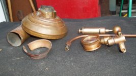
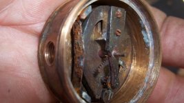
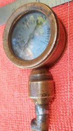
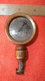
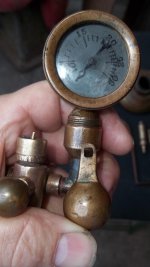
The gauge is interesting, to say the least. I believe I saw one very old steam pressure gauge which used a corrugated diaphragm to work the mechanism. As pressure increased, the diaphragm deflected and worked the movement of the gauge. The gauge on this engine and boiler is quite a fine piece of work, and I have to wonder if it were a one-off job. Making a Bourdon tube which would function properly over the range of pressure to be measured, and fit into a small gauge case may have been something Mr. Baugh was unable to do, so he resorted to a different means of sensing steam pressure. Usually, there is a hairspring in mechanical pressure gauge movements, and I wonder if there is a hairspring that is missing from this gauge. I can imagine at the time Mr. Baugh built this steam plant, he may well have gone to a local watchmaker or horologist and asked him to make and fit a hairspring to his gauge movement. He may also have handed the gauge face off to a local engraver for engraving/etching. Different times when a person could go to local craftsmen for one-off out-of-the-ordinary type jobs, and when local foundries would pour one-off jobs like castings for a steam engine model.

As per your style, you have done another exemplary job of bringing the engine and boiler back to first class condition. Mr. Holly, New Jersey is down in Southern NJ, close to Philadelphia, PA. It is a busy area, suburbia, with people living life at a hyperkinetic pace. Crazy traffic, the usual "homogenized" kind of community that is proliferating our country and taking away the individuality and local flavor. It is hard to imagine Mr. Baugh living in Mt Holly at a time when life was slower and machinists, horologists, foundries and places with steam engines (where Mr. Baugh may well have worked) existed.

When Lester takes on one of these steam plants, he shows a respect for the person who made it, and does not take "the easy way" to get things running again. The result is what I call "museum quality" restorations and repairs. At the rate Lester Bowman is going, he could open a small museum of the collection of small steam plants he has taken on and restored and repaired.
 
All the little plug cock's leaked badly on the boiler. Also the Water level cock's pointed "outward" rather than down away from the operator. The way the boiler was plumbed to the engine resembled a toy and operation resulted in pools of water all over the base. I wasted no more time messing around with these fitting's and refitted using vintage 1/8" npt cock's and larger valve's. I hated to change the original fitting's but I like a steam engine to run and operate without being scalded by faulty valve's and fitting's !

Here is a short video of the newly piped steam plant running in our kitchen sink, Yes..wife was ok with it and made sure the water level remained in the middle of the glass by working the boiler feed pump :)

Here is a short video to welcome in the New year.

YouTube
 

Attachments

  • 100_5163.jpg
    100_5163.jpg
    70.3 KB · Views: 54
  • 100_5162.jpg
    100_5162.jpg
    79.3 KB · Views: 59
Lester & all the good folks who participate in the 'board:

HAPPY NEW YEAR !! I was watching Lester's youtube of the "Baugh" steam engine and boiler as 2019 ebbed away. Earlier today, I had done my usual thing for the New Year- I had rigged a 20 foot pipe mast with a 1" Lunkenheimer steam whistle outside our garage, and connected it to the 120 gallon shop air tank. 165 psig showing on the gauge. After watching Lester's youtube, I got my old Ithaca Model 37 shotgun and a couple of shells, and my nephew (about to start his first machine shop job)and I went outside the garage. My nephew stood by with his phone to give me a time signal. On the stroke of Midnight, I cut loose with the whistle, quilling it and making it sob and yip. Then, I let off two rounds with my shotgun, and resumed playing the whistle. In between whistle blasts I heard the "whoop" of a police car, the flashing light came on down at the foot of our road, and the officer hollered: "Happy New Year" over his loud hailer. I daresay, seeing Lester's little boiler with its scaled down whistle had me chuckling. The echo of a 1" Lunkenheimer whistle, even blown on air, echoes nicely up and down our valley. After the whistle got a little hoarse from lower air pressure, we went into the house, had our traditional shot of rye whisky, hugged and kissed and called it a night.

Reading Lester's post about the chasing of leaks on model or small sized pipe fittings is something I can relate to. I recently bought a steam cylinder casting from a fellow in Illinois. It cleaned up to 2 7/16" bore x 3" stroke, and I am designing an engine around it. The steam chest casting has "lugs" where the chest studs pass through, rather than straight exterior walls. The result is not much room for a steam chest drain tapping. I used 1/8" NPT for the cylinder drains, but with no room on the steam chest, I went for 1/16" NPT. It is a little known/little used thread. Taps and dies are available for it at low cost. Swagelok makes some fittings in 1/16" NPT. Swagelok also offers tube fittings down to 1/16" outer diameter tube in brass and stainless. I am making a fitting with 1/16" NPT male to screw into the drain tapping on the steam chest, and the other end of the fitting is 1/8" NPT to take a brass petcock.

As for the engine I am building, I decided to build a "working" sized engine rather than a model (built a few of them over the years). This will be a center-crank engine, vertical, with a marine style frame, crosshead guide, and marine style con rod. The mainframe parts will be welded fabrication, machined to final dimensions.
I plan to use poured babbitt bearings for the mains and con rod big end brass. I had a chunk of truck axle from a (deceased) neighbor's old tow truck. It went into the firebox of the coal boiler the other day and was fully annealed by slow cooling in the ash can. I know I could (and should) just go order a chunk of good steel of known composition, but somehow, using a piece of old truck axle and knowing the fellow who had the tow truck it came out of seems more acceptable to me. It's an engine that is "kinda, sorta, happening" with sketches done on the kitchen table at odd hours, reviewed and stamped by one of our cats with a paw print. No CAD, no Solidworks, just sketching, figuring, a few odd engineering calculations, then figure the setups and fixturing to hold the parts... then go make the chips. I suppose someday, some future collector will be looking at this engine and wondering who made it, what he was thinking, or what he was all about... That's the inevitability. Lester, thankfully, finds these one-of-a-kind engines and respectfully repairs and restores them and returns them to steam service. I hope there will be someone like Lester, in a future generation will be around to take one or more of my engines and scratch his head and undo the ravages of time and/or neglect and then try to figure out who the guy was who built the engines.
 
Joe ! I'm really glad you've taken on this steam engine design and build project. I'm VERY sure it will be very well built and perform flawlessly. I'm excited to see some picture's of it one of these day's.

Now..I have a lot of stuff like draincock's and some really nice small drip oiler's which you may need. I also have some nice flywheel's which might be suitable for your engine. Tell me what you're looking for and I'll forward to you.Let me know :) This stuff is hard to find but it also needs to be used by a real Engineer on a real engine.

Happy new year to all !

PS.. Joe Michael's. You must sign and date this engine you're building :) This way it will ALWAYS be connected to a most worthy Engineer and writer of some of the most interesting story's and memory's I've ever read.
 
Last edited:


Back
Top