What's new
What's new

Early 1900's Cincinnati No 3 Horizontal Mill

sanderson231

Plastic
Joined
Jan 25, 2017
I bought this machine about 10 years ago and finally have enough time to restore it. Retirement is great.

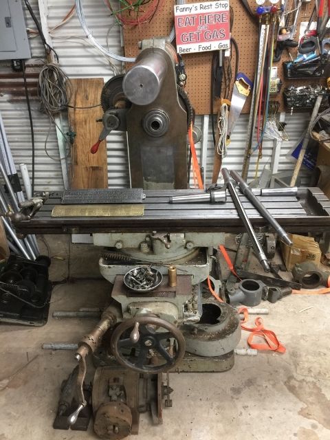
From what I know this machine is from the early 1900's. The spindle is #11 B&S. The nose of the spindle is threaded. There is a slotted collar that screws on spindle that can drive an appropriate arbor. The machine has a two speed back gear. With counter shaft speeds of 145 rpm or 260 rpm and the three step cone pulley, there are 18 spindle speeds ranging from 13 rpm to 350 rpm. The table feed is from a transmission in the bowels of the machine. The transmission is operated by two levers; A or B and C and D as well as a pin with four positions. This gives 16 feed rates ranging from 0.007" to 0.310" per spindle revolution.

Hear are a couple of pictures of the machine:


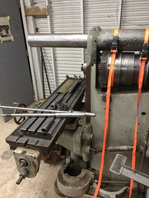
The problem I am having in disassembling the machine is getting the spindle out. I removed a large set screw from the cone pulley which locked the cone pulley and the two rear back gears to the spindle. The cone and gears now turn freely on the spindle with the spindle held stationary. The spindle turn easily in its bearings. But when I try to pull the spindle out something is preventing it. I suspect it is some type of thrust bearing mechanism that is getting in the way. There are two lock rings on the spindle just ahead of the gear that drive the transmission. I built a hook wrench and was able to get these lock rings free. They are both threaded. Pics of these lock rings below:


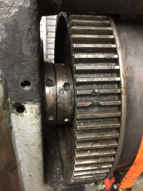
The left ring appears to hold the front spindle radial bearing (flanged on front) in place. I suspect the right one is for thrust adjustment. When I try to pull the spindle as shown below then I can no longer rotate this lock ring even though it was hand free before putting an axial force on the spindle.


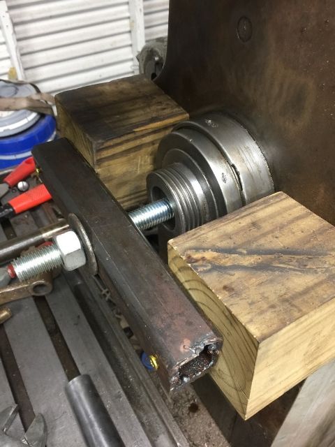
I believe that the front radial spindle bearing needs to come out so I can get to the thrust mechanism. I tried pushing it out by rotating its lock ring counterclockwise as much as I dared. It wouldn't budge. Soaked it with Kroil and will try again tomorrow.

Anybody have any other thoughts on how to get the spindle out?
 
Have to back off on nuts as spindle incrementally comes out - as noted, pulling on spindle with any force will make turning the nuts difficult

Front journal will be tapered

Probably should drop the "S" on nuts - only the one nearest the bull gear is on spindle. The one near column is on "box", or front bearing

Assume spindle is a reasonably tight fit in bull gear

On Edit - looking at scan, it appears the steps would be:

1. Remove pulling force
2. Back off nut
3. Block gear against column
4. Apply pulling force closing gap opened by backing off nut
5. Repeat
 

Attachments

  • Spindle Cone Scan 1913.jpg
    Spindle Cone Scan 1913.jpg
    37.9 KB · Views: 458
Last edited:
John, the thumb nail you posted looks very close to what I have. The only difference I see is with regards to the back bearing. On my machine the rear bearing is threaded on the outside on both front and back. On the front end there is a lock nut. On the rear end there was either a locknut or cap with a hole in it for the drawbar. This part is MIA. Below are pics:


On the front of the machine your drawing seems to be exactly what I see. Although not labeled on your drawing, the left lock nut in my previous post threads onto the outside of the bearing box. This keeps the bearing box in place (flanged on front). The right lock nut is threaded to the spindle is for loading the tapered bearing. Again although not labeled there is a washer on the spindle that is captive between the lock nut and a bearing face on the back of the bearing box.


I was able to easily push the spindle out about an inch by turning the right lock nut counterclockwise until I ran out of thread. Below is a pic with the spindle partially extended:


Next I strapped the spindle up to keep is centered in the bearing and try to pull it the rest of the way out with my home made puller. It moves a little but then something binds up. After it binds I can no longer rotate the spindle. However the two lock nut are still loose. I can jiggle the gear a bit (slop in the key/keyway). The cone pulley and the back gears are also loose on the spindle. There is nothing related to the rear bearing that should prevent the spindle from moving forward. Maybe something related to the washer between the locknut and the back of the bearing box?
 
I had a #1 from around 1906 that I pulled the spindle on. I think you have to pull the front bearing out because the key will not fit out threw the bearing hole. Mine did bot have back gears but the cone pulley was keyed to the shaft. Your gear should be keyed to the shaft.


Sent from my iPhone using Tapatalk

I've Kroiled the bearing box for several days and put as much force on it as I've dared trying to remove the spindle. The bearing box should have come out. My supposition is that it was a press fit to begin with and that coupled with a little corrosion over a 100 years means I'm probably not going to get it out.
 
Do you have the lock ring loose on the front bearing? It has been awhile since I had mine apart but I thought the lock ring on the front bearing would push the bearing out. You have to have the spindle lock ring loose so the bearing lock ring can push on the spindle lock ring, bull gear and pulley. The front bearing is held in with a lock ring.


Sent from my iPhone using Tapatalk
 
They didn't give overly detailed instructions on spindle removal.


View attachment 189867

This is from an earlier machine where the table feed was from a gear on the back of the spindle. So that gear would obviously have to come off to get spindle out the front. Once that is off then the spindle should come out the front as long as the spindle adjustment lock nut is loosened at the same time. Pretty simple as long as everything is in good condition. Since I don't have the feed gear on the back of the spindle, all I should have to do is loosen the spindle adjustment lock nut. Doing that I was able to push the spindle out about an inch until I ran out of threads on the spindle. When I tried to pull it the rest of the way, it's no go. Which leads me to believe that something is not as the machine came from the factory.
 
I gotten the bearing retention lock ring loose. I tried to push the bearing box out with it at the same time pulling on the spindle which should push on the back of the bearing box. As much force as I dare without bearing something.
 
I found a picture in my 1916 "A Treatise On Milling And Milling Machines". I think the key in L is hitting the front bearing. IMG_1620.JPGIMG_1621.JPG


Sent from my iPhone using Tapatalk
 
The pictures are not very clear. In the reading it says the only key is in L which is the bull gear. The shaft, where the key is has the same diameter as the small end of the bushing so it will not go threw the bushing with the key in the shaft. Hope this helps.


Sent from my iPhone using Tapatalk
 
There will be a key in the spindle for bull gear that is traveling along with spindle. Try and see if it is hanging up on anything

Can't see anything. I'll try tomorrow to feel around with a thin piece of metal.

Your drawing shows a key way going nearly the length of the shaft until there is a diameter reduction that appears to be less than the bottom of the key in the bull gear. So that should allow the spindle shaft to come forward as the key slides through the keyway. Maybe the key is sheared off and the bull gear is no longer clock correctly with the keyway.
 
Did a little more checking today. First I locked the spindle in position then tried to rotate the bull gear by tapping on the teeth with a block of wood and a hammer. Bull gear seemed to be locked to spindle so I think this eliminates a sheared off key.

Next I reinstalled the spindle then removed it with puller backing off the spindle adjustment lock nut as I went. Got the spindle out about an inch and something bound up. Once it binds I can no longer rotate the spindle. I checked the bearing retention lock nut, the spindle adjustment lock nut and the thrust washer (between the to nuts) and all were loose. I was able to jiggle the bull gear a little like there was a little slop in the key and keyway. I was able to probe with a feeler gauge between the spindle adjustment lock nut and the bull gear. I was able to feel the key way in the spindle. There was no key in it. So I think the key stayed with the bull gear as the spindle moved forward. I'm pretty much baffled at this point. Gonna have a friend from San Antonio come up and see if he can anything.
 
Been busy landscaping but finally got a little time to get back to this project. Got my friend from San Antonio up to see if I was missing something on spindle removal. He was stumped two. So it appears that there is something wrong that can't be seen - maybe something that is not letting the bull gear key slide in the keyway in the spindle. We flushed the spindle bearings with plenty of oil and the spindle turns smoothly so the plan is to leave the spindle in place and get the machine cleaned up for manual operation, hang a motor on it and see how it performs.

So next step was to remove the table. That was pretty straight forward after removing the lead screw. Here is a picture of the operation with a lifting yoke I fabbed up with tubing laying around:


I would like to take the saddle off to get down inside the knee for clean-up and recon. It appears that the swivel table has to come off to get to four screws that are holding a casting to the bottom of the saddle. So did a little more fab and modified yoke to pick the swivel table as seen in following picture. I put a little pressure on it with the hydraulic lift but didn't seem to want to come off. Anybody got any tips on removing the swivel table?

 
Happy to report success in removing swivel (universal) table. I applied a little tension with hydraulic lift then rocked table with lifting yoke. Repeated this several times and finally it pops loose. Here is a pic with the table lifted off:


An interesting feature on this machine is how the swivel table is clamped to the saddle. This is done with three T-studs. These studs are tensioned by horizontal taper pins as seen in the picture below:


I'm pretty excited to get swivel table off. The removal of the saddle looks pretty straight forward. That will allow full access to inside the knee. One mystery to be solved is the shaft for the manual vertical movement. As of right now this shaft has no means of retention so when cranking to raise or lower the table the crank must be pressed in to maintain gear mesh. Doesn't seem right. Hopefully I can see something when saddle is removed.
 
1-1/4" of rain today so got some time to play in shop. No pictures but happy to report great progress in getting parts off the machine. All the parts removed look to be in great shape. Removed the drive shafts and most of the gears for the three power feeds. Removed the lead screw from the saddle. Removed the gib for the saddle and the saddle is loose. Just need to get four slotted screws loose to drop a casting holding a spur gear off the bottom of the saddle. The screws did not budge with a large screw driver so I Kroiled them to sit overnight. Could really use a drag link socket 5/8" wide and 1/16" wide. These don't seem to be available in this size so may end up grinding down a larger one.
 
Got the screws loose that were holding the casting on the bottom of the saddle by leaning hard on the screw driver and turning the blade with a crescent wrench. This allowed the saddle to come off. Removed the rest of the parts that could come off in preparation for rolling the machine out onto the covered garage apron for pressure washing and paint removal. Plan to build a temporary enclosure to contain the lead paint. Finally I found a missing collar that locks the shaft into the knee for manually cranking the Z-axis so will have to make one. Below are a couple of pics of the machine stripped down.


Back
Top