What's new
What's new

Early lathe - rack driven

esbutler

Aluminum
Joined
Oct 14, 2013
Location
Sloansville, NY
Here is the second installment following up on https://www.practicalmachinist.com/...ory/two-very-early-lathes-cheap-ny-cl-351289/

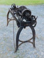
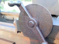
I confess one obvious aspect of this lathe didn't even click with me until I started picking out some pictures to share this evening - the cone is opposite of almost all other lathes. The steps get bigger as you get farther away from the spindle nose.

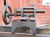
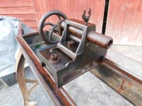
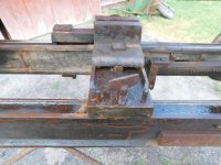
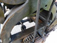
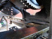
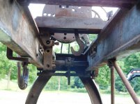
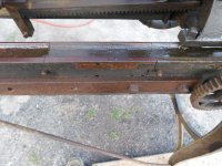
Here are some overall shots.
 

Attachments

  • DSCN0312.jpg
    DSCN0312.jpg
    96.6 KB · Views: 339
  • DSCN0313.jpg
    DSCN0313.jpg
    97.3 KB · Views: 224
  • DSCN0315.jpg
    DSCN0315.jpg
    96.4 KB · Views: 211
  • DSCN0316.jpg
    DSCN0316.jpg
    97.8 KB · Views: 203
  • DSCN0303.jpg
    DSCN0303.jpg
    96.9 KB · Views: 226
And the carriage - dog-legged, rise-and-fall, weighted. The dial on the front is graduated and numbers are prick punched. A later addition?
 

Attachments

  • DSCN0276.jpg
    DSCN0276.jpg
    95.7 KB · Views: 181
  • DSCN0301.jpg
    DSCN0301.jpg
    97.3 KB · Views: 137
  • DSCN0323.jpg
    DSCN0323.jpg
    96.2 KB · Views: 133
The head stock end...

The belt carries the power down to drive the worm that ultimately drives the rack that is connected to the carriage. The bar that has the horizontal slots (and is connected to the later-added portion of a brake lever) has two studs fixed to it. One has the driven pulley and a spur gear connected to it. That spur meshes with another on the other stud. As the assembly is shifted to the left or right, one or the other spur engages the cog wheel which in turn drives the worm shaft forward and reverse. Is that cool or what?
 

Attachments

  • DSCN0287.jpg
    DSCN0287.jpg
    95.3 KB · Views: 135
  • DSCN0286.jpg
    DSCN0286.jpg
    95.8 KB · Views: 120
  • DSCN0285.jpg
    DSCN0285.jpg
    95.8 KB · Views: 120
  • DSCN0284.jpg
    DSCN0284.jpg
    94.9 KB · Views: 117
  • DSCN0283.jpg
    DSCN0283.jpg
    96.9 KB · Views: 122
and some shots of its nether regions...

The rack is too short to stroke the full distance between the spindle nose and the tail stock when it is out at the end of the bed. It looks like there may have been a rod that bridged the rack to carriage connection and could reposition the available stroke up or down the bed.
 

Attachments

  • DSCN0290.jpg
    DSCN0290.jpg
    92.4 KB · Views: 113
  • DSCN0293.jpg
    DSCN0293.jpg
    95.3 KB · Views: 119
  • DSCN0295.jpg
    DSCN0295.jpg
    92.9 KB · Views: 124
Sometimes you do what you have to do... apparently someone had a need for some extra swing and made a temporary gap bed with a hack saw, a drill, and a hammer.

"Don't worry Dad - I'll put it back. It'll be good as new."
 

Attachments

  • DSCN0304.jpg
    DSCN0304.jpg
    95.6 KB · Views: 150
  • DSCN0322.jpg
    DSCN0322.jpg
    93.6 KB · Views: 136
That must be one of the most unique machines of any type I have ever seen.Hopefully these features ( other than the gap) will make it's origin known.
 
Peter noted another example of a lathe with cog/pin type gearing in the https://www.practicalmachinist.com/...he-corn-field-241922-post1766400/#post1766400 thread (if I did that right that's a link directly to his post #112). Interestingly that lathe was made in NY State - East Beekmantown, Clinton County in the shop of John Rea. That from another book I need to get for my library. A quick scan of it online cites the shop in which it was made saying it was in operation "during and for many years prior to the civil war" but it doesn't specifically date that lathe.

Although we don't know where this lathe was made (yet? ok, probably never will), I will mention that it came out of a machine shop in Greene, NY in the 1970s. No idea how long it was there. The seller could not remember the name of the shop or proprietor. I add that here in hope that someone, likely knowing nothing about machine tools, will be searching the internet regarding some aspect of Greene history and stumble onto this and provide some related information. Hey, you never know...
 
It's good that the leg butcher's didn't get it. That is a museum piece. Though I hope you get it all working. The guy that drilled and cut the bed didn't have any machining skills or common cense. He may have done that damage with only hand tools. I wonder if he got the benefit from his effort.
All the builders from that era didn't have as many other machines to steal ideas from.
 
Last edited:
That is a cool lathe, thanks for saving it. I seem to remember another rack feed lathe on here but I can't remember any names. It had a rack like yours that moved with the carriage.
 
I know at least one of these pictures has been posted here before.

American Machinist

This 1916 article in the American Machinist records a few lathes it dates back to the early 1830s at W.&B. Douglas in Middletown, CT. Some of these I believe are rack driven with the bigger hand wheel on the front left and a worm and worm wheel under the head stock. These share the three- and four-leaf clover motif with the one in this thread. I think that was a common enough spoke design in that period that this doesn't mean much in terms of identification but still interesting.

BTW, part two of the article starts on P. 591 in case you're interested. If you do go there, note that the captions are swapped between figures 9 and 10.
 

Attachments

  • American Machinist article 1916 - figs 1,2.jpg
    American Machinist article 1916 - figs 1,2.jpg
    97.6 KB · Views: 117
  • American Machinist article 1916 - Figs 3,4.jpg
    American Machinist article 1916 - Figs 3,4.jpg
    93.5 KB · Views: 80
I have read that article. Very in depth. Lots of firms and textile mills machine shops were turning out machine tools by the 1830s. Many copied other designs and added their own special touches. The corn field lathe has a twin which resides at the moffet mill in R.I. The clover shapped gears I have seen on many different machine tools of that era by many different builders.
 
Its interesting to note that while the method they chose to separate the gap looks rather crude, with the drilling and fracturing it from the bed, it's actually quite ingenious from a functionality standpoint. In doing it this way you dont lose any height from a cut and the two pieces will key back to each other nicely, the same way fractured cap connecting rods are made.


Back
Top