What's new
What's new

Figuring out this putnam

Rule_So_Hard

Plastic
Joined
Apr 10, 2015
I have a 1870s putnam. 6.5' long overall. When.i purchased it it came with a load of parts and fortunately in the load of parts came all the threading gears.
Unfortunately I could never quite figure out how to make the threading mechanism work. After looking and all the pictures I could find I couldn't quite envision it but recently my buddy bought a putnam similar to mine and we were able to get out eyes in it and realized the parts we needed came with the lathe and I've been looking at them all along.
Two problems we've run into...
#1 they hacked together the carriage drive by make some hacked up form of a pulley driven off the idler instead of the spindle. I now see there is supposed to be a flat pulley on the spindle to drive the carriage. I need to figure out the size of this pulley so Ican get my carriage drive correct.
#2 they for some reason made a idler spacer with a steel bushing instead of brass and then pulley on the idler is slightly over sized. Not a huge deal because I have to make a bushing or buy a bushing anyways.
 
Feeds were commonly off what ever turned on the left end. All you are trying too do is make a chip

THREADING has to be off spindle - via suitable gear train - and has to move carriage by LEAD SCREW using half nuts that close around the screw. Since one rarely completes a thread in a single pass, it must be an exactly repeatable process

Since we can't SEE the lead screw on this one, it must be in the bed out of sight - or maybe on the BACK

Englathe.jpg

We can see the little three step cone pulleys which are EXCLUSIVELY for FEEDING

On this extension bed gap Putnam - we can see the feeds belted up and ready to go - and also note the lead screw is somewhere else - maybe on back

IMGP1377.jpg

Here is one of the how to threads on posting photos on this forum

Posting Pictures on the South Bend Forum

have fun
 
#1 they hacked together the carriage drive by make some hacked up form of a pulley driven off the idler instead of the spindle. I now see there is supposed to be a flat pulley on the spindle to drive the carriage. I need to figure out the size of this pulley so Ican get my carriage drive correct.

Actually, on my 1860ish Putnam which no doubt is similar to yours, the "lay shaft" is directly under the machine spindle (and driven by gears contained within the headstock that do not include a "tumbler reverse") the shaft of which comes out through the left bearing support and has both a step pulley (on mine a "round belt step/cone pulley) AND a gear there on the outside. The pulley is on the inside of these two and lines up with a matching reverse cone pulley on the front bed mounted "feed rod." The gear is on the outside (leftmost)position of this lay shaft and lines up with gears put on the "banjo" (gear sector) which can pivot on and lines up with the rear-mounted lead screw gear.

The gear/thread chart refers to the gears placed on the banjo. My chart is marked with three columns of numbers: the left most column refers to the TPI to be cut, the middle column refers to a gear placed on the lay shaft, the right column refers to the gear placed on the lead screw. Another gear is usually placed between the two gears named, but this is frequently called the "stud gear" and is placed on a moveable stud on the banjo. It can be ANY gear not named for the TPI, just so long as it reaches both of the gears named and connects them. Its only purpose is to "reach the distance" between the lay shaft and the lead screw shaft. The banjo can swing on the lead screw and the stud can move on the banjo to adjust for center-center distance of the gear train generally. The banjo is held in place by a slotted sector and bolt holding it to the headstock.

My Putnam lathe is very early for its features. The gear/thread plate is hand-stamped and while the numbers line up well, it is apparent it was done with a straight-edge and manual alignment/pacing. The Putnam Machine Co. plate shows a patent date of 1863, but this same plate was used for many years starting in 1863 and up until the lathe headstock pattern changed about the time of the 1876 Centennial when the Putnam name was then cast into the headstock.

#2 they for some reason made a idler spacer with a steel bushing instead of brass and then pulley on the idler is slightly over sized. Not a huge deal because I have to make a bushing or buy a bushing anyways.

The thread/gear chart on my 1860ish Putnam do not include the possibility of "compound gearing" - rather the entire chart is laid out without compound gears specified - which would include ANOTHER column to show the two compound gears and their ratio together.

This is not to say that it was never done. A machinist needing a particular thread cut and not finding it on his chart might "devise" a gear train to make it happen - and this gear train MIGHT include a compound gear which would be placed on the stud gear position, the two gears of the compound gear being fixed together on a keyed bushing. Appropriate "offset bushings" would be required to maintain correct alignment between gears.

Putnam in your case might have designed a compound train into the chart. But the chart would have to show a pair of gears together which was frequently done with a slash to separate the input from the output gear of this mated gear pair. It is done this way on the Barnes Lathes.

My Putnam (not complete) is the classic 14" swing x 5 foot bed - perhaps the smallest "regular" size they made of this very standardized, widely applied, and commonly available lathe. Putnam with this lathe kind of set the pattern for the industry for the next two generations of machinists.

Hope this helps. I could provide pix of the headstock/banjo area of this lathe if that will help.

Joe in NH
 
I'd love to see a picture of that joe. The parts we found for the "banjo" pulley are definitely the correct ones and the evidence is clear that the carriage is fed off the spindle like the one posted in the photo above. The spindle gear has a clearly custom spacer and the gear is incorrectly spaced in comparison to the rest of the machine. When I say hacked I mean they tried to weld aluminum to a steel spacer and used a bunch of set screws. It was really bad haha.
As far as the compound gears...my threading plate is definitely hand scribed so it's hard to say if it's original or not but I have all the gears and it definitely matches up to the correct thread per inch count. I'm trying to get pics up but it dlseems more difficult from mobile.
 
attachment.php

attachment.php

attachment.php

attachment.php

attachment.php

attachment.php
 
Your lathe VERY similar to mine, but I would say from the thread plate a little later. A "rise & fall" lathe saddle, it is probably not of the weighted lathe convention but rather the "pinned raising screw" type which counts on the weight of a saddle/carriage and possibly "gibs" to keep the saddle/carriage to the lathe ways. The half nuts lever handle (which appears bent in the pix) is used to engage the half-nuts and yours is fortunate to have a long handle which aids the operator.

Keep in mind this lathe has no "thread dial" (i.e. a dial used to signal the operator the correct time to engage the half nuts in cutting a thread) but is of the 19th century type which once the lead screw is attached to the carriage via the half nuts, is left attached for the entire time threading is done. To cut deeper on a threading pass requires "backing up" the entire lathe to the thread starting point and simply "cutting deeper" on the next pass - repeatedly - until the thread is formed full depth. This method of use was "de-rigor" until the development of thread dials possibly in the late 1880s.

I'll tell you the downside of reversible motors in this application as we get closer to actually discussing threads.

Your "banjo" appears to pivot on the "lay shaft" - which I have not seen in any of my antique lathes, but this is not to say it is not original. It may well have been since the principal of swinging the arm and adjusting the stud gear position remains the same.

Your feed rod pulley (front bed corner) appears original and would have been used with a "round" sewing machine type leather belt. The matching aluminum cone pulley is a nice replacement and may in fact be made to work quite nicely using a round belt - but is not original, of course and I expect previously an A section V-belt may have been used in lieu of the only slightly more difficult to find round belt stock (I recommend Page Belting of Hooksett, NH who are a bit pricey - but will get it right on perhaps a $30 belt.) The positioning of the pulleys/gear appear original - what I can see.

2nd thought on this. The banjo appears to have been moved from the more normal lead screw position - the boss on the banjo "blocks" the full use or normal placement of the usual round belt upper cone pulley, or at least the upper pulley would be misaligned were it in place.

I will follow this up with some pictures of my same areas a little later today.

It looks like it is well worth restoring on its own merits - they don't make them like this anymore - have not for 140 years, and Putnam WAS the name then in this type of lathe - and still is...

Although Lathe & Morse is a close second. The two companies were related by marriage...

You can imagine how this goes ca. 1860. "My brother works in Worcester at a Machine Company - he's a nice guy..."

Some things don't change...

Joe in NH

I thought that little brass dial in the picture where you can see the lead screw engagement was the threading dial. That's how I was using it at least. Engage in the same number to land the tool in the same spot on the part.
The carriage does have a reverse engagement on the apron. Basically you have tool feed, carriage feed, The clutch for the carriage, and the reverse engagement.
That aluminum pulley they had rigged onto the banjo pulley instead of the spacer for the banjo pulley. It took me and my friend 8 years to figure out the correct way to install it so we could have lead screw engagement. I've made quite a bit of parts on it that way but it always suffered from belt slippage on heavy cuts. Eventually their rigged pulled busted and I figured it was time to fix it right. It been a year of staring and tinkering to get where we are now. It makes nice clean finish and parts well also. I've even power tapped with it.
Our plan was to machine a pulley to go on what you're calling the lay shaft to drive the carriage. From the photos I've seen that's the proper configuration. Then it'll be able to run the carriage feed or lead screw without taking things apart.
I cut some threads on it and they turned out "good" but the surface was rough so I need to work on proper tool setup for that.
 
I thought that little brass dial in the picture where you can see the lead screw engagement was the threading dial. That's how I was using it at least.
The little do-hickey appears to be an "add-on" of a most useful kind. Perhaps also the long half nuts engagement lever I mentioned earlier. The original lever was perhaps 6 inches long and placed so the operator would have to pass to the rear of the lathe to manipulate it before or after cutting the thread to completion - no "on the fly" as original conceived. So the changes all make sense.

Apologies on the pix. Verizon is playing games with their online Texting and I'm not able to pick up a pix taken with my phone. Tomorrow I'll try the camera which gives a better pix AND can use the memory card into the computer directly.

Be patient with me.

Joe in NH
 
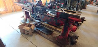
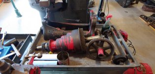
Here is a quick pic of the Putnam sliding gap bed lathe we are restoring at the Tuckahoe Steam and Gas Association machine shop museum (302 Found).0220211015.jpg0220211016.jpg0220211015a.jpg0220211016a.jpg


Back
Top