What's new
What's new

Friction disc replacement on 1920's lathe?

darneson

Plastic
Joined
Jan 1, 2018
I have an Elmco lathe that is part of a testing station. It is the 34A and has really interesting variable speed system where you can move a friction plate along the radius of a cast plate on the motor and increase or decrease the speed on the spindle. It has the original table and motor still and the tachometer so you can see how fast your a spinamathinging. You can see more detail about it here: Elmco Lathe and Electrical Test Stand

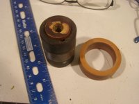
The issue I am trying to solve is that the friction disc is old and has been exposed to grease and dust over the years and looks like it needs to be replaced. It appears to be made of thin paper or cardboard rounds stacked up and bolted together. Has anybody seen something like this before or have an idea of how to replace. Only info I am finding is related to snowblowers and lawnmowers. I could replace it with something rubber perhaps?

img1.jpg

006.jpg
 
You could try glueing up some untempered masonite and turning it to size. Masonite is cheap, and a paper friction disc will be very expensive.

I was going to suggest something similar. If those are clamping rings as I suspect you won't even need to use glue, just drill, clamp, and true up.

Is there a chance that the old discs are made of something like paper-phenolic?
 
Hello Darneson,
Very interesting to see your Elmco lathe - the friction disc looks to be different (wider) to the one on my web page. Might you be able to email me some high resolution (2 to 3 MB) pictures of your lathe and its drive? I'd be keen to add them to the Archive. My thanks, Tony. lathes.co.uk My direct email: [email protected]
 
I would start with a bath in lacquer thinner or acetone to remove any oil/grease from the paper disc. If that does not get the disc driving the lathe properly, collect cereal boxes until you have a stack thick enough to match the original. Put the new cardboard into the old metal parts and true up the O. D. in a lathe.

Paper pulleys for flat leather belt drives were very commonly used in diameters smaller than the laminated wood pulleys of the day. It probably had to do with decent performance at low cost compared to cast iron or fabricated steel pulleys. But you see all sorts of old pulleys, so there must have been a competition to keep costs down, along with low vibration and good friction.

The drive I constructed for my flat belt lathe has a large wood pulley and two smaller paper pulleys and several cast iron pulleys. The paper pulleys were worn unevenly when I got them, but were very easy to turn true. I used the shop vac to suck up the messy dust while I turned them.

Larry
 
Had a friend who was working maintenance dept in last few years with my old company back in 1970s. We had a number of larger engine lathes that were getting outdated even then. A clutch needed replacing and parts were no long available. He suggested and it worked well to take it to brake shop that has the choice of material as mentioned above and the ability to attached it to the original clutch plate. Don't quote me on the parts as I was not involved. But the point is that Limy Sami posted a source that I know worked in a similar situation. Think my friend said it cost like $15 or something like that to get that lathe clutch resurfaced and put that lathe back in operation until it was retired permanently. I am sure the shops that can still rivet and glue brake and clutch linings do all sorts of off the wall repairs for all the machines out there that have no parts support any longer. Good luck. John.
 
I would not call that a friction clutch, but just a variable speed drive. I was working on a machine a few months back with a similar drive arrangement, the problem with it was that the outside diameter of the sliding wheel had worn to a point it no longer had adequate pressure on the steel disk. The wheel on this machine was made of a linen phenolic/micarta. I turned down outter diameter, then turned a ring of paper phenolic to fit over it, and epoxied in place. So far it is working well.
 
Curious, what controls the pressure between rotating disk and the sliding wheel? Machine I worked on the rotating disk was spring loaded, sliding wheel was on a fixed shaft. It looks like rotating disk on your machine is mounted to motor, is there any way to increase pressure between them?
 
I believe this is what you need. I have a 1913 Metz Model 22 Roadster and this is where I (and other Metz owners) get their pulleys remade. Send them the whole unit and they'll send it back refurbished.

Paper Pulleys

home
 
Tony,

Sure thing I will get you some pics of what mine looks like. PM me with whatever you are really interested in as far as angels etc. It needs a good cleaning so as long as that is not an issue...
 
I thought I was crazy when I thought it was made of paper and survived for almost 100 years....I can't believe that it is not only a thing but that you can still get new ones!
 
Anyone know what/how the paper pulleys are made? Is it just pressed paper? Or do they bind it together with glue/epoxy like phenolic/micarta?

You could probably use paper or canvas micarta, but considering it is not exactly cheap stuff, it might be cheaper to send it to the paper pulley place, IDK. And if you can adjust the spring pressure, maybe move motor forward, it might work as-is

Dug thru my pics and found a few of the machine I was working on. IIRC in this application the shaft was powered and the phenolic wheel drove the disk.
 

Attachments

  • vn303 13.jpg
    vn303 13.jpg
    91.9 KB · Views: 145
  • vn303 18.jpg
    vn303 18.jpg
    97.9 KB · Views: 152
  • vn303 19.jpg
    vn303 19.jpg
    86.4 KB · Views: 111
  • vn303 20.jpg
    vn303 20.jpg
    83.9 KB · Views: 113
No idea yet. There is no spring or lever that I can see that would adjust the pressure between the pieces for drive. I would guess you would have to make adjustments to the motor location to keep it correct...
 
Check where the disk mounts to motor shaft, on machine I was working on it took decent pressure with 2 hands to push on disk and feel the spring loading. It has to apply pressure somehow, otherwise it would be slipping shortly after being placed in service.


Back
Top