What's new
What's new

Hendey #2B Universal Restoration - Phase 1

Dr. Hillbilly

Aluminum
Joined
Dec 6, 2019
Location
Oregonia, Ohio
I drug my Hendey home from MN. Now the works starts...
I call this "phase 1" because it will be the longest lasting phase so I need to start working on it first. I can do the easy stuff in parallel.
My Universal is missing its indexing table. Does anyone know of a Hendey index table available? I fear not, so I assume this phase comprises the modification of some other table for use.
I want to be able to cut worm and helical gears, so I need the following attachments:
2.JPG4.JPG
3.JPG1.JPG
Images are courtesy of the Torrington Historical Society (they gave me permission to post them)
I have been following the recent posts for the Cincinnati No. 2 addressing a parallel subject. So I need to source a table and build a gear plate with an adjustable link, and angle plates to orient the centerline of the table in the Y-Z plane, the X-Y plane, or the X-Z plane.
Practical_Treatise_on_Milling_and_Milling_Machines_p059_a.jpg
Any templates, drawings, suggestions, or warnings are welcome.
 
suggestions

I am going to be a suggester of you using known terms

Never saw an "indexing table" but Dividing Heads are fairly common:D

Makes all the difference in the world in the process of looking for something

Here is a Hendey page of long ago - using that terminology - but showing gearing for differential indexing rather than spiral or helical milling

Hendey DH.jpg
 
I am going to be a suggester of you using known terms

Never saw an "indexing table" but Dividing Heads are fairly common:D


Thanks for the suggestion/correction! Please continue to do so.


So to rephrase:
1. I could use designs of riser-blocks and angle plates for mounting of the dividing head in various orientations and various heights
2. I could use designs of gear-plates (probably the wrong term again)to support the gear-train to the dividing head.
3. designs for gear-plates with extra idlers to support an dividing head on a riser.
4. which dividing heads are compatible with my Hendey-Norton? (used on the left side of the table, appropriate size for a No.2, etc.)

In every case an available component would be preferred to making one from scratch.
 
which dividing heads are compatible with my Hendey-Norton?

B&S mounts that end - for one. Scan from Practical Treatise on Milling and Milling Machines - by them. You can tell by the input shaft pointing at us (often referred to as the "PTO")

20191231_125350_050.jpg
 
If I remember correctly, mine is right where the overarm comes out on the right side. I don't have a picture handy and can't get to the shop right now. I'll look tomorrow if you don't find it.
 
My Hendey Norton 1 1/2 drives the table from the right ( facing it). The table screw at Left side, is where the gearing fixture is. It is timed to the feed for spiral. Unless I'm having a stroke, it was difficult to find a universal dividing head driven from the left. Many could be used but the dividing plate would face backwards.
Might be that advent of the double rams, changed all this. The L-O Chuck heads are neat. A friend of mine has a beauty but it is semi universal.
 
Dr. Hillbilly:

I think that I answered a few of your questions in a PM, but it is possible that I am thinking of someone else. Since your questions are
typical of the questions I get regarding the Hendey Milling Machines, this would be a good time to post this information.

To the best of my knowledge, there are no surviving production records for the Milling Machines, whether Plain, Universal, Lincoln or
Oscillating type. Milling Machine production appears to have started in 1900, about the time Planer production stopped. The newest one
that I have been able to date from the drawings was built in 1929, which is about the time production stopped. It is owned by Brett at
Custom Machine and it features a NMTB 50 taper instead of the more common Brown and Sharpe Taper. Even with the Serial Number, a production date is only an estimate. I have heard various locations for the Serial Number, but I still haven't found it on my own No.3
Universal Miller.

About two weeks ago, I sent you a copy of the Parts Book for these Cone Head models, which featured a picture of the 2B Universal Miller
as a frontispiece. If You will refer to Sheet Seven and Sheet Eight, you will find a complete breakdown of all of the parts used in and
with the Dividing Head. Please use the part name when asking questions about any Dividing Head, it makes it a lot easier for Forum
members to answer your questions. Refer to Sheet Nine for the additional parts used for Differential Indexing, including the rather hard
to find Raising Block, which is also used for drilling operations.

If you will compare the Brown and Sharpe Dividing Head to a Hendey Dividing Head, you will find that for all practical purposes they will
interchange. The size of Dividing Head for a particular size Hendey Miller is as following: No.2 Miller uses a 10 inch Dividing Head,
the No.3 Miller uses a 12 inch Dividing Head and the No.4 Miller uses a 14 inch Dividing Head. The Index Plates used on the B&S Heads
and the Hendey Heads seem to be the same, but there is a slight difference in the Change Gears. When it comes to Differential Indexing,
as long as you have the proper gear combination, it doesn't really make much difference which table you are using. For Helical Milling,
refer to the Table of Leads for Brown and Sharpe in the American Machinist Handbook.

You may be lucky and find a 10 inch Hendey Dividing Head and the necessary gears. I am still trying to find a 12 inch Hendey D.H. for
my Hendey No.3 Universal, but until I do, I am using a Brown and Sharpe 12 inch D.H.. Over the last few years, as time has permitted,
I have been making a list of all the Hendey Milling Machine drawings that are on the microfilm (very few hard copies have survived).
Eventually, I would like to put together a portfolio of drawings for each size and type of Hendey Miller, including the Lincoln Millers
and the Oscillating Millers. I had to make the missing bits and pieces for my No.3 because the chance of finding them was very remote.
If you decide to make the pieces you need, given a bit of time, I should be able to find the necessary drawings. After fifty years of
running my shop, I plan to shut down at the end of April, it should give me more time to work on my own projects. If I can be of further
help, let me know.

Hendeyman
 
OK, I will quit looking for a serial number, and I will look for a B&S 10" dividing head in parallel to searching for a Hendey head.

The reason I wanted the serial number was to better identify spindle drawings.
There are many excellent posts on this forum regarding repair of the lathe spindles, but I found none for the mills. The milling spindles seem fundamentally similar, so I was hoping to identify which lathes were close and could be used as a guide.

My spindle is sized (I think).
I thought it might be the simultaneous engagement of the cone-pin and back gear, but the cone spins freely when disengaged.
I also thought it might be an issue with table feed, but there should be a bit of lost motion in the chanin and feed gears.
I will feel really stupid if this machine has a spindle lock which I have accidentally engaged. Is there a spindle lock?

The machine has not been used for 30 years, but it was under power briefly 30 years ago and again 2 years ago, and was free then. As I should not be dealing with 100 years of corrosion or a crashed and bent spindle will judicious use of a dead-blow free it? If so do I tap from the rear, and how hard? (I am accustomed to spindles with ball-bearings so the thought of hammering on a spindle makes me cringe)
 
Shows the same Ball shaped covers on inspection ports and oil fills well below spindle C/L - makes me suppose it is quite similar to Hendey lathes that are ring oiled - a ring rides on the tapered journals and brings up oil from the chambers beneath the journal

Here is your photo

Hendey 2B Spindle Lube.jpg

And here are the usual scans I share with folks trying to get their Hendeys going again

All parts.jpg
Front detail.jpg

List.jpg

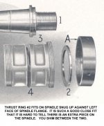
Parts together.jpg

If the mill has the equivalent of ring nut "L", it would seem backing that off a half a turn and bopping the rear of the spindle with a hefty dead blow hammer might be worthwhile to see if such unsticks the tapered front journal. A prelude to this might be several days of getting light oil into the inspection port on the front bearing

I'm fairly sure any ring nut has a binder screw that has to be backed off before attempting to turn that ring nut

Note above procedure is in no way a FIX, it is merely a TEST to see if spindle can be unstuck
 
Dr. Hillbilly:

Regarding the Milling Machine Spindle, it is very similar in design to the Lathe Spindle, but there are a least two differences that you
need to keep in mind. The length of a given size of Lathe Spindle may not fit a given size of Milling machine. Comparing drawings is the
only way to be sure if one will fit the other. The most important difference is that a Lathe Spindle is ground internally for a Morse
Taper and the Milling Machine Spindle is ground internally for a Brown and Sharpe Taper. Since the smallest B&S Taper used on the Knee
Type Milling Machines is a No.10 and the closest Lathe size would be a 16 inch model which would use a Morse No.4 Taper, which is not
an exact match. Instead of trying to change Spindles, it would be much easier to make the standard adjustments and shim the Spindle.
Keep in mind that all of the Hendey accessories for your Miller, except the Porter Cable Vertical Attachment, use the B&S No.10 Taper.

Hendeyman
 
The spindle lives!

Inspection ports now lubed...
Collar L does have a screw (now loose)
Collar L backed off 1/2 turn (by hammer and punch, pin holes already wallowed so no damage could be done and a pin spanner would have no chance)
Just to confirm that the outboard end of the arbor was not seized in the outboard support I removed both.

My biggest dead-blow did nothing

Backed off collar I (after loosening set screw. Dead-blow did nothing.

Backed of front bearing collar A, and one more blow freed it.

It seems to rotate smoothly now, but not effortlessly.

One option is to:
return the collars to the correct preload.
Turn the spindle in back gear at very low rpm to get lube everywhere
Turn the spindle faster and check heat
If no heating assume that I got lucky?

Other suggestions?
 
suggestions?

Get the chambers under the journals cleaned out as much as possible. After 90 years probably just black goo in there. Some lathes had THRU holes (out the back) and some did not

The recommended lube (by myself) is Velocite 10, an Exxon Mobil product. This is a very light bodied spindle oil

Here is Pat's photo showing his no nonsense approach to the cleansing

DSC02429.jpg
 
All I need is a tank big enough for a 3100 lb. machine! (I wish my headstock came off)

The upper inspection ports look beautiful, no gunk at all.
The lower ones have smaller fittings so I cannot see anything without a borescope (so tomorrow I buy a borescope!)

Do any of the previous posts on lathe spindles address the adjustment of the collars I backed off?
 
Do any of the previous posts on lathe spindles address the adjustment of the collars I backed off?

Not likely - all those threads are about correcting a problem with the front conical bearing and its thrust face. Thrust face wears and allows conical journal to bind in its bearing. It is necessary to fix that, and it does not involve adjustment

These pages may suggest something. Page twenty-nine talks about taking up end play but fails to tell us what that value should be. Probably as little as possible and still not cause heating. ON EDIT: A test could be put the ring "L" back near where it was and see if the spindle still turns freely. A front bearing in good shape thrust face wise should allow this to be tightened up solid and still not stick the front conical journal - after "L" was backed off a bit to create maybe .002" end play. After backing off "L" a bit results in a stuck front bearing, you can assume the mill has the same ailment as most of the lathes do at some point in their life. We have referred to this ailment as HENDEYITUS. :D

1940 Hendey Op Man_16.jpg

Here are both the 1920 and 1940 manuals - thanks to Greg Menke for hosting these for me

http://pounceatron.dreamhosters.com/docs/hendey/1920-Hendey-manual.pdf

http://pounceatron.dreamhosters.com/docs/hendey/1940-Hendey-Op-Man.pdf

ph
 
Last edited:
Snugging collar A left .040" play.
Snugging I and L gets it down to .005"
Still seems high...


Here is a page from when Lucas (Horizontal Boring Mills) still had plain bearings. Second paragraph promptly goes into end play values, but then this in a machine that weighs four times as much as your Hendey, so gives at least an idea of how you are doing

Lucas Plain Bearing Info.jpg


Back
Top