What's new
What's new

just got a CVA Mill - have questions

Rudd

Stainless
Joined
Jul 30, 2003
Location
savannah, jaw-ja
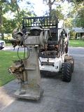
I just got the mill shown on the forks into my shop. I am looking for any info, a parts breakdown would be great. It appears to be in good to very good but very dirty condition, so I am not planning on tearing it down. I did find a nice patch of babys**t green paint under the added on start switch, so I may have the color decided!

Click on thumbnails to enlarge.


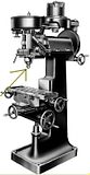
Tony's lathes uk site shows a newer model - I've ganked some images to illustrate my questions.


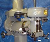
Shaft at "A" is approx. 1" dia, has a left hand thread, and will protrude on the opposite side of the head when screwed it. I cannot determine what it does.

Collared shaft at "B" does not go completely through the head, again, what is it's function? Split collar is threaded on with an SHCS to lock it. Possibly a bushing adjuster? Early models had a partially split bronze bush at the lower end of the spindle according to the lathes uk site.

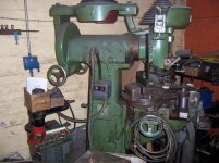
At "C" I have a hex nut that will rotate about 30 degrees either way - then hits what feels like a hard stop. It does not lock the collet in place. Machine uses 3C collets. Mine looks more like the B&W image than the photo of the nicely painted machine. I can't feel anything happening inside the spindle at the collet seat when this nut is turned. I don't want to force it.

Above this is a LARGE knurled collar at the bottom of the head which I suspect retains the spindle vertically, i.e., it looks like the spindle comes out through the bottom of the head.


And finally, the later model mill had a capstan rack and pinion arrangement to slide the massive ram in and out. Mine does not. I've gotten mine to move just a skoch by prying, but it looks like it would take Popeye to move this in and out on a regular basis.
Things are beginning to free up some with liberal application of the magic fluid (oil) - the machine had been sitting 24 years or so in a garage. The ram looks like a poser though.

I got the original motor (British made Newman) which has no info other than the maker. I have no idea what voltage it might want. There's a Westinghouse 220/3ph on it right now. A VFD is in my immediate future either way, so if I can figure out the brit motor, I might reinstall.

Thanks
Rudd


Thanks
Rudd
 
Last edited:
Hi Rudd, I've got one! no manual or any documentation though, mine is a split bush spindle bearing and has a morse taper 3, i think the later ones with the bearing race have an int 30 spindle. not a bad old machine and i still make money on mine! contact me if there is anything i can help you with.
Croz
 
Hi Rudd

I have one here in the UK as well..mine is still in bits for transportation.. I also know somebody over here who has one that he uses on a regular basis.

BTW mine is green..but I'm not sure that it is the original colour.. my friends one is a mid dark blue.
CVA went on to assemble/ build Milwaukee/K&T mills over here in the UK..I know of one of them as well and its also in this nice dark blue-and it looks original...

How did yours get over to the states?..never thought that they exported them..
Need to get the motor reconditioned on mine..its a special flanged job.
Be careful with the belt pulleys..they are a cast alloy and one of mine is chipped..the metal looks like it will chip easily if you pry on it or drop it...

All the best

John
 
OK, if yours is disassembled, do you have any ideas on the functions of the parts marked "A" and "B" in the center photo? Do you have the same spindle nose as indicated on the B&W drawing?

I picked mine up in an estate sale. The man moved "down heah" to Georgia from New York. He had been employed as a machinist at Pratt and Whitney, he retired and opened his own shop in NY, then moved it all down here and did not manage to get a new shop set up before he passed away. Most, if not all, of his equipment came from the big Pratt and Whitney "garage sale" back in the 1970s', so that may be where this machine came from.

I saw the pot metal pullies. My first thought was be careful, those are bigger than the swing on my lathe.

I have 2 motors, the original Newman, and the westinghouse that's mounted on it. Both mount properly with the oddball flange arrangement. It looks like someone made an adapter for the westinghouse. What sort of power would the newman be looking for? 50 hz? voltage?

Edit, after working in a windowless defense plant where everything but the floor was painted baby**t green with yellow trim, the color just looks right to me. My house is that color with yellow trim in fact. Makes it easy for my friends to find.
 
CVA Type 79 Parts ABC

Rudd

I'm not sure that I fully understand your questions-forgive me if I get it wrong..

I'm not sure what the bar A does. I might simply be a handle to move the top trapeziodal slide along-but i think that it might be for attaching something to measure depth on the work table. eg a gauge ...its a diesinker mill.

B surely is the collar holding the end of the quill down feed pinion...there is a cone clutch done up with the big wing nut on this so that you can either use lever down feed like a drill press or disengage this to use the fine down feed on the front of the head for the milling quill.

Not sure what you mean by C you seem to be pointing to the clarkson autolock chuck. This probably has a no3 morse taper shank which is held in place by a threaded drawbar. I seem to recall that it has a knurled end with a tommy bar hole..look on top of the drive pulley-unscrew it a couple of turns and tap it with a soft hammer-in theory the chuck complete with shank should drop down a short way..then you unscrew the drawbar..from the top.

When this is removed the end of the spindle is nearly flush with the head casting..
Reading this thread makes me realise that there may be a 30int version out there but I think most are MT3... please forgive me if you already know this..

I have included some shots showning the original motor as found and the mill as I found it at the back of a workshop..not very good pictures..


Regards

John
 

Attachments

  • DSCF1521.jpg
    DSCF1521.jpg
    94.2 KB · Views: 1,059
  • 100_8149.jpg
    100_8149.jpg
    95.6 KB · Views: 1,859
  • 100_8155.jpg
    100_8155.jpg
    95.1 KB · Views: 598
CVA Type 79..morethoughts

Rudd

re read you message to see if I had missed something....the machine does use 3C I remember my friend showing me the collet holder...but this is like an adaptor sleeve with a 3MT outer..not sure about the nut you mention..might be some way of jacking the sleeve down to release it

if the motor is like mine it'll be 415 volt 50HZ 3 Phase..mine is in storage and i cant check the plate right now.

As the pinion shaft is disconnected by the cone clutch operated by the large four lobed wing nut-its in two pieces which might explain your thoughts.

Hope this helps

John
 
3c is a strange collet to find in a mill. It was common as a small lathe collet.
Chances are there is some kind of drawbar retaining an adaptor taper. It may be a bit of a chalenget to pop it loose if its been in place for a long time. Some tapers like the 9 B&S or morse tapers are self locking. The drawbar should be set up to push the taper out as well as pull it. Trying to drive a self locking taper out with a hammer is a sure way to kill your spindle bearings in short order. Been there done that, bought the bearings. You can use the hammer technique on R8's or National machine tapers. They are not self locking and pop free with a light blow.

I have seen 50hz motors run on 60 hz current, and thats basicly what you ask the motor to do when you hook a VFD to it. The frequency difference should not deter you from useing the original motor in a hobby shop. Voltage is another issue. You might look a the number of leads on the original motor and see if you can set it up. If it has three leads, its single voltage and will be tricky to decypher what voltage it is. 9 leads and you have a dual voltage three phase motor. 6 leads and you have a dual speed motor, single voltage. If you have the 9 lead option, then there are plently of folks on this forum to help you sort it out. If its single voltage its going to take a little more work to determine the proper voltage.

Another thing to consider, you are dealing with an AC motor. Most likely it will operate a little under 3600 or 1800 rpm with a 60 hz input. In the UK the same motor on 50hz will run a little under 3000 or 1500 rpm. That meens you spindle speeds are a little higher than intended. Not a big deal and you have lots of shives to chose from but you low end may not be as low as you need for large drills or fly cutting. You may also want to use the very highest speed range with caution, because it will overspeed the machine. Its not likely to be a problem, but it is 20% over. Also any tables of RPM's or feed rates from the manufacturer will be off by 20%.
 
Older motors from the UK are not likely to be dual voltage, so probably 380/415 Volts 50Hz. I believe when you make the switch to 60Hz, the correct voltage will be 440/480 Volts.
 
OK, it gets progressively wierder.

the machine came with collets marked 3C on the nose. Yeah, but the threads are on the wrong side. :eek: Again, click on thumbnails to enlarge. A 3c has threads on the OUTSIDE from any I have seen offered for sale.


that is a 1/2" x 12 tpi thread on the inside. I understand that 1/2 -12 is std practice on the eastern side of the pond where this thing was made. I checked the drawbar, it may be 55 degree threads, can't tell, my gauge seemed to fit fine.


The drawbar passes right through the spindle , which is about .560 id, to engage the collets. Every Clarkson Autochuck I can find is held in BY a drawbar, the drawbar does not pass through it.


This is the business end of the spindle. The large knurled ring will unscrew to reveal the bottom of the bronze spindle bearing. it wont come off, the nut is in the way. The nut will turn pretty easily abut 1/6 of a turn either direction and hit what feels like a hard stop. Feels like it's supposed to be in one of the two positions, like there is some sort of detent. I hate to get really heavy on it. It seems this nut has no purpose in life other than preventing the large knurled ring from coming completely off, or making me nuts (ier). If it's supposed to "jack this adaptor out" - which way? CW or CCW?

I ran a small rod down the bore of the spindle, and cannot feel any step like this ... thing.. is some sort of adapter into a MT3 or other taper.

This must have been a going set-up at some point, I got a Bridgeport No. 2 boring head that obviously goes with it, in the original case.

So, has anyone else seen oddball 3C collets like this?

The nutted thing that's making me nuts - what is it? Is there maybe a MT 3 hidden in there somewhere?

Anyone know the OD of a 3C drawtube by chance? Hopefully less than .560, but I bet not.

And I think one final bit of irony, I made a crude 1/2 -12 tap to clean some threads up on an old printing press abut 2-3 weeks ago.. glad I kept it. :rolleyes5:

BTW, Ahall, FWIW, my little horizontal is set up that a retaining collar takes the blow from the hammer, not the bearings. It uses B&S 9. This one sees to be the same, large internally threaded split retaining collar at the top of the spindle.
 
3c with an 1/2 x 12 internal thread.

Thats not the 3c I am farmilear with.
Have you looked at the collet page in a current machineries handbook or Collets and tried to verify the collet is actualy a 3c, and not some kind of shop made hybred.

It is entirely possable someone modified a standard collet to meet there needs.

Also, more modern production 5C collets have internal threads as well as external threads to allow for the positioning of a collet stop. Good chance some makers of the 3c have done the same thing and someone may have used this to there advantage, although 12 tpi seems a little corse.

Given that the #3 mt is not retained by a drawbar, its probably held in by its own locking taper. This could be an SOB to get ahold of and draw out without distroying it. The oddball collet is a bit of a red flag indicating someone went to a lot of effort to keep this machine going and probably had a good reson for it.

If you think you have to get it out, consider disassembling the spindle entirely and inspect the spindle carefully before proceding. Its possable someone wedged in an adaptor to fix a cracked or otherwise dammaged spindle. You may wind up doing more harm than good trying to get it out.

Assuming you conculde removing the taper adaptor is a good choice, worst case, bore the adaptor out or weld a nut into the center of it and build some kind of bearing puller to extract it.

Take your time making that call, and weld with the bearings removed. Running welding juce through the bearings is not to good for them.
 
Thats not 3C

Rudd

that is definitely a weird form of collet that you have got there-the sign that you think is 3C is in fact two upper case letter Cs back to back and intertwined -which is the symbol for the English firm of Crawford-who made lots of collets for most of the english manufacturers including Holbrook and pattern collets for american lathes inc my Rivett..Hardinge et al

The number 123 is the type number for the collet...I still feel sure that you have got MT3 in there as the basic taper in the spindle..

it will be long winded but the only way is to contact my other friend who has the CVA with what I believe is an original CVA collet holder..send him the pics..and he only has occasional email access and ask his advice.... somewhere I have an old crawford catalogue..need to dig it out

I will try but it will take a little time..

Regards

John
 
Cripes! Wotcherman, you are right. My eyes may be going. FWIW, the "123" looks more like a "128" live and in person. And it's on every collet.

I'm trying to wrap my head around some sort of puller, I agree, I think pulling the spindle is the next thing if you can't find out any information. I'm not sure if I can pull the spindle and get that knurled ring out of the way without first removing the adapter. If I can, then I could get some purchase on the spindle nose for a puller.

Tony's site Page Title clearly shows a spindle for an early machine without the adaptor in it. I've found with my little sheldon mill though that there can be any number of variations from what's published as an "early model" or "late model", not to mention the endless factory options.

Wotcherman, I am in no great rush, but I would be very very grateful for any info you and your friend can provide.
 
Ok I Think that I have it...

Got hold of my friend-yes it is the factory collet holder...

The collets are held by a threaded draw bar only that is introduced down the spindle from the top. If you remove this -you are right... you cannot tap a drift down from above as there is no register. The method of removal of the collet is to part unscrew the threaded drawbar and tap on the end..guess you know that...

The big nut is solely to jack the holder out of the morse taper socket in the spindle.
Do NOT screw it downwards-it is captive as you say and not meant to come off from this direction. Screw it upwards till it stops-then get a nice SNUG fitting spanner and use a soft hammer-give it a good tap to wind it further upwards and apparently the holder should fall out of the morse taper onto the block of wood that you have put there for the purpose on the table...(you obviously have removed any collet and drawbar that are in there first.)

Might be an idea to put some plus gas-or maybe you guys do Kroil(I mean penetrating oil) down the spindle first to see if some will bleed into the taper.

The bronze collar is nothing to do with the collet holder. This is the cover seal for the bronze bearing bush which is drawn into the bearing housing by a big screw which will be visible when you remove the cover-much like a cataract lathe bearing.

good luck and let me know how you get on..

Regards
John
 
My friends response afterlooking at the photos..

Rudd....my friend got to down load the photos this afternoon and I quote his response:

Hi John,
I have just down loaded your photo's, and the collets on the CVA are original. To remove the Collet Holder from the spindle, No.3 Morse, just screw the large nut clock wise, as if you are running up a nut.The process should jack the holder out.It must be without a collet in the holder to work, and set the spindle clamp to hold the spindle from turning. If he finds the spindle has back lash, you have to remove the top pulley, and hub. Then you can adjust the end float on the spindle, the adjustment screws are square heads, two of, tighten to remove the back lash. Good Luck.
Best regards Alan.

My description was quoted directly from his phone call ..he mentioned the use of a copper or hide mallet on the stout snug spanner..

The 'spindle clamp' is the large clamping device on the side of the main spindle pulley..now you can see why it is there...

as I said good luck and give us some feedback as to how you get on...

Regards
John
 
Hail Britannia, God save the queen, etc.., maybe we made a mistake when we kicked you guys out of the country!
I've give it a try and let you know. I searched last night for several hours, and found that these collets are not even listed on Hardinge's BIG BIG list of collets. MT3 I can deal with. Unobtanium collets are a bit scary.

thanks
Rudd
 
unobtanium

unobtainium collets are one thing .....

Rudd.... I darent even risk losing one screw off this when you are in the UK..there are only five known examples over here


and as for a follow rest i should think that there will be a queue in the US let poor old me in the uk if one of those turns up on ebay,,,


All the best

John
 

Attachments

  • IMAGE_416.jpg
    IMAGE_416.jpg
    88.9 KB · Views: 297
I've just acquired one of these beasts - an early version, completely caked in grime and grease.

Took a bit of a punt on it as it was cheap and will be a useful addition to my shop once in better shape.

The spindle has had a hard life. Appears to be straight though the morse taper is scarred and bell mouthed. Probably typical for a machine of this age that hasn't been particularly well cared for.

I'm trying to remove the spindle to have it re-ground (currently running around 2 thou out of true nearest chuck). I've removed the pulley mounting boss - any idea how to remove the threaded collar circle in attached image? It has two holes at 180 degrees and I have tried turning it using a large set of circlip pliers. It also has two square headed bolts. Do these somehow keep it for rotating? Wanted to check before going out to find/buy square headed sockets.

spindle.jpgThanks!


Back
Top