SAG 180
Titanium
- Joined
- Sep 17, 2007
- Location
- Cairns, Qld, Australia
So my Graziano SAG 180 would be a 1950's vintage machine somewhere in her 60's I guess. Recently I surface ground the cross slide base and the top of it where the compound slide is attached after noticing the compound was rocking during heavy cuts and squirting oil out from under it. My skills with a surface grinder are sorely lacking and I didn't "spark out" the surfaces I ground, but you could see the surfaces had worn a lot and in the case of the compound base had significant corrosion. With the aid of a small 2' granite flat and a 6" diameter cast iron flat I was able to get the ground surfaces fairly flat with a thin faint layer of blueing. I found a 60 degree oil stone and stoned the worst of the grooves and gouges in the saddle dovetail and refitted the cross slide and compound with some shims on both tapered gibs.
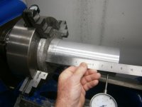
The improvement in surface finish is night and day as the toolpost/compound base and cross-slide are tighter fitting. I had a consistent 3 thou taper getting wider at the chuck on a 4" diameter aluminium tube about 9" long. I rechecked the bed with a level and found a slight twist at the tailstock end of the bed and adjusted the jacking bolts to remove it and now I get a 4 thou barrel shape bulging in the middle of the tube with exactly the same diameters at both ends.
Any suggestions for tuning out a barrel shape?.
Last edited:
")