Glitch
Plastic
- Joined
- Jun 7, 2010
- Location
- North Carolina
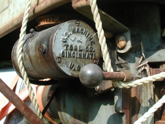
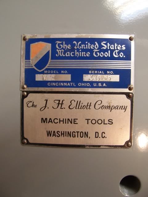
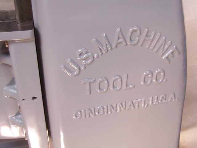
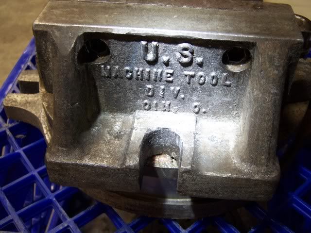
Meet “Bertha”, my U.S. Machine Tool Co. Model VT milling machine. This machine and a South Bend Heavy 10 lathe of similar vintage fell into my lap in 2010. The lathe was functional, but the mill was in need of attention. Most of the work was done late at night and in the wee hours, as I was spending most of my available daylight time on a protracted house-building project. I found the machine restoration therapeutic, despite having to endure much good-natured ridicule and jokes about “the other woman” from my family.
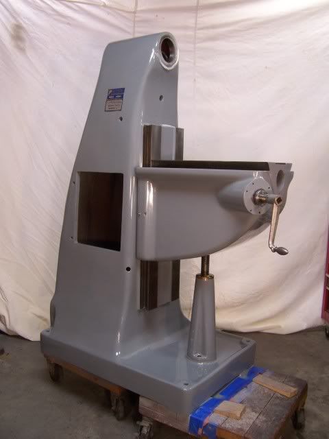
The mill is a World War II era machine that was purchased by the Physics Instrument Shop at Duke University. It was eventually replaced by more modern equipment and relegated to the “Staff Shop”, where Physics faculty and students can use the machines to work on their projects. After years of abuse there it was finally deemed surplus and ended up on a trailer parked in the new owner’s yard.
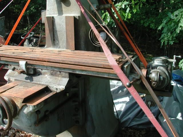
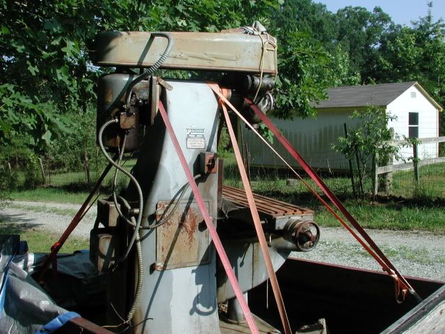
This is Bertha as I first encountered her, having never been unloaded by the previous owner, who passed away shortly after obtaining the mill. Attempts to keep her covered with tarps were futile, and most unpainted surfaces were pretty well rusted. The spindle turned, but not smoothly, suggesting that water had made its way to the bearings.
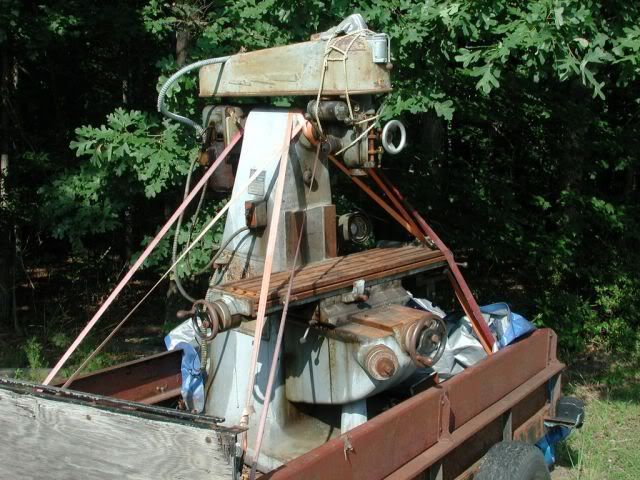
So, clearly she was in rough shape, but I enjoy a challenge and the price was right ($100). I was able to hitch the trailer to my pickup and anticipated an uneventful drive home of about 5 miles. I had the lathe in the bed of the truck, and the mill weighs about ¾ of a ton, so I was pushing the envelope. As soon as I pulled out on the highway my power brake booster died, rendering the brakes ineffective. I forged ahead, downshifting to slow down for traffic lights, and made it home without killing myself or anyone else. I wanted the machines in the basement of my woodworking shop, which has a grade level pedestrian door in the back but no easy access. I got neighbor guy to drive his little rubber-tracked backhoe over, and with the help of some more neighbors we manhandled the lathe through the door without too much trouble. The mill was much more challenging, as the backhoe wanted to tip over on its nose if the mill was lifted high enough to avoid dragging it. We ended up kind of dragging it down the slope to the door, and set it on some heavy-duty dollies that I had made. I had previously removed the table to allow it to fit through the door, and we horsed it in.
At my leisure, I completely disassembled Bertha with the exception of removing the knee. There were a number of revelations during this process, one of which was that the knee was completely packed full of brass, aluminum, and plastic chips, fused by hardened coolant and oil into an industrial fruitcake-like substance. There had been a pin projecting from the underside of the saddle that had both acted as a travel stop for the saddle and engaged the sliding steel plates that are supposed to keep debris out of the knee. One of the inmates at the reform school must have rammed the pin hard enough to snap it off, which made the sliding plates only semi-functional and periodically allowed a large gap for junk to fall through.
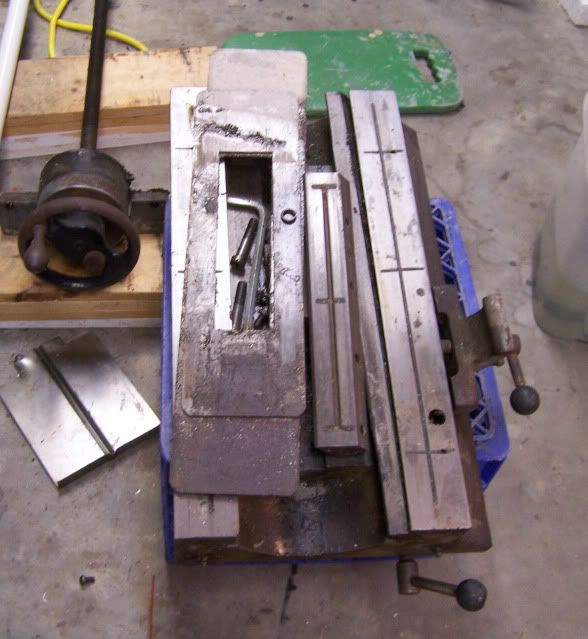
Another revelation was that someone used grease to lubricate all of the zerk fittings on the saddle, table, and knee, rather than way oil, so all of the oil galleys were clogged and there was a nice abrasive paste on all of the ways and a bit of scoring. Some of the pieces after disassembly:
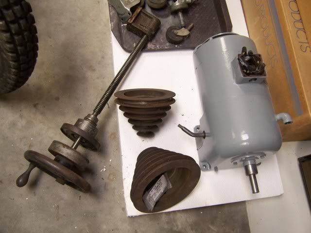
Pulleys, saddle feed screw and handwheel next to Lima drive gear motor (motor already repainted):
Saddle, sliding saddle cover plates, table feed screw:
As feared, water had reached the spindle bearings and corroded them enough to make them unusable. The old bearings were class “0” precision Timkens and no longer manufactured. After much searching I was able to locate a class “3” cone and a standard precision cup from W.C. DuComb Bearing in Detroit to replace the upper bearing. The lower bearing is unobtainable in class “0”, and it appears that the only modern use for that bearing size is in aircraft landing gear. I was able to purchase a Timken cone and cup from Sky Geek in LaGrangeville, NY. They are FAA approved! For those interested, these bearings have a 20629 suffix, indicating that they are specially selected as “prime lot”, honed, and roughly correspond to precision class “2”. I also replaced the two “pulley sleeve” bearings with readily obtainable Nachi components. Total expended on all bearings was about $200.
Spindle receiving new bearings:
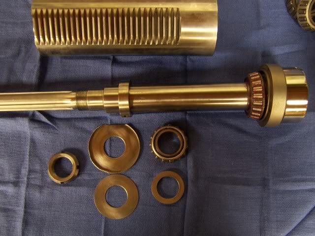
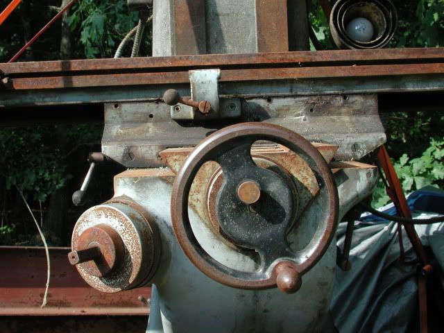
The feed screws for the saddle and table were found to be in inexplicably pristine condition after I cleaned the crud off of them. The bronze nuts are adjustable, and I was able to get the backlash down to just a few thousandths on each. I adjusted all of the table, saddle, and knee gibs by trial and error and am very satisfied with the result. The saddle gets a little tighter at the extremes of travel due to wear in the middle of the ways, but it is pretty much irrelevant to me. The bronze bushings for the knee elevation crank were worn into ovals, but they were easily replaced.
Saddle feed screw and knee elevation shaft and bevel gear after clean-up:

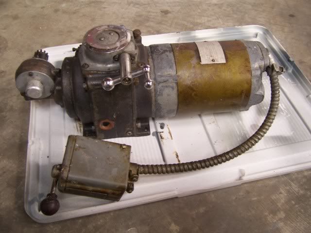
The mill has its original motor, which is mated to 4-speed gearbox known as a “Lima drive.” The gearbox had been weeping oil around the shift lever, so I replaced that seal and the motor shaft seals and filled the tranny with Mobil1 gear lube.
The motor is 1 horsepower, 220v 3-phase, and my shop only has 220v single phase power. I am a novice with motors, but I did my research and learned about variable frequency drives (VFDs). It was a 100% no brainer to go with one of these rather than a rotary phase converter. I used a TECO JNEV-201-H1 to power the motor (Dealer’s Industrial Equipment, $131). This is actually a “sensorless vector drive”, which is supposed to maintain full torque regardless of speed. The motor is now variable speed, rendering the Lima drive transmission and step pulleys unnecessary. The tranny can be left in 4th gear and the belt can be left in one position for eternity. This little VFD replaced about 25 pounds of electrical apparatus that had been bolted to the back of the mill.
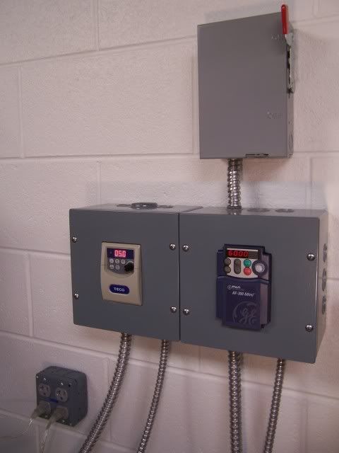
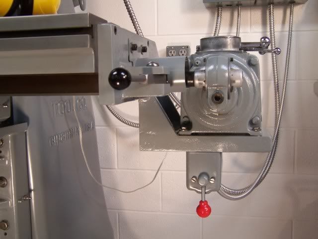
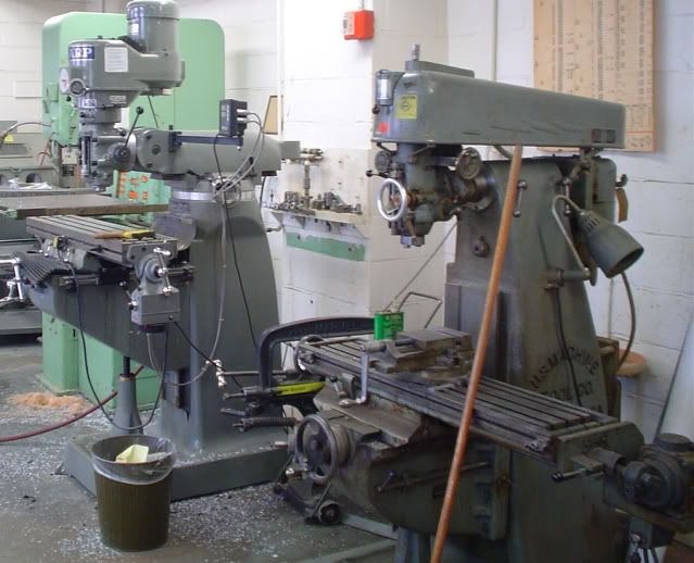
Bertha also has a power table feed, which has a 1/4 hp 3-phase motor and a bizarre and obsolete variable speed mechanism known as a “ring roller”. There is only one source for the special oil that this mechanism requires, known as “traction lube”, and it is $100 a quart! I did some research, learned that similar technology is used in certain automotive continuously variable transmissions, and the lube for them is only 8 bucks a quart. I bought some, and it seems to work perfectly. To supply 3-phase power to the motor I obtained a ‘last year’s model’ General Electric Model D7206 VFD from Dealer’s Industrial for $31. It is the blue one on the right in the pic above.
Ring roller power table feed:
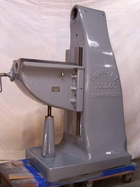
The mill’s main casting, knee, and head were riddled with chips, and the paint and underlying filler in the coolant pond under the knee were blistered from water pooling there. I bought a cheap needle scaler at Harbor Freight that made quick work of the blisters, and I used Bondo and red oxide putty to fill the defects. The repair sites were primed and the entire casting was then wet-sanded. I sprayed the knee, body, saddle, and misc. other parts with Valspar industrial enamel from Lowes using a $10 spray gun from Harbor Freight. The head and motor were painted using a brush. The access door and the belt guard were too rusty to be worth fooling with, so I made replacements out of aluminum diamond plate.
Most of the rest of the restoration involved de-rusting parts with the help of Evapo-Rust, wire wheels, sandpaper, and glass bead blasting. Anything chuckable, including the solid steel cylindrical ram, was mounted in a lathe and sanded and polished to remove rust and pitting. The 42”-long table was so rusty that I took it outside and lightly sandblasted the top surface, then polished it up with mesh abrasive pads on a hand held grinder. The table, saddle, and knee ways cleaned up pretty well with light polishing with mesh pads.
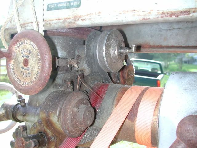
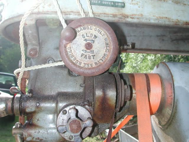
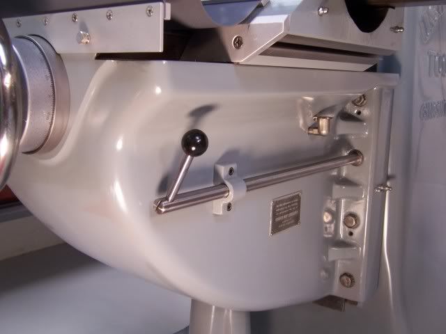
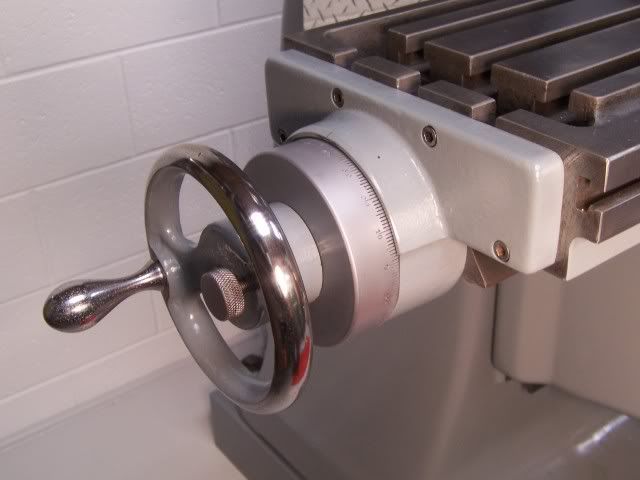
If you look closely at the “before” pics, you will see that there was a power downfeed gizmo that ran off of a timing belt from the spindle. Unfortunately, like so many other aspects of the machine, the timing belt is obsolete and unobtainable. I have found 2 other people in the U.S. who have the same mill, and one was nice enough to take a pic of his timing belt for me. Even with the Uniroyal (now Gates) part number, the engineers at Gates can find no evidence that a belt with that pitch ever existed. I doubt if I will be needing a power downfeed, but I have all of the parts and I suppose I can make new pulleys that will accept a contemporary belt if I need to. The mill has two manual downfeeds--a drill-press-like lever on the left side of the head and a fine downfeed handwheel on the front. These are selected by engaging or disengaging a clutch via a knob on the right side of the head. The fine downfeed is sweet--I can turn the handwheel with one finger.
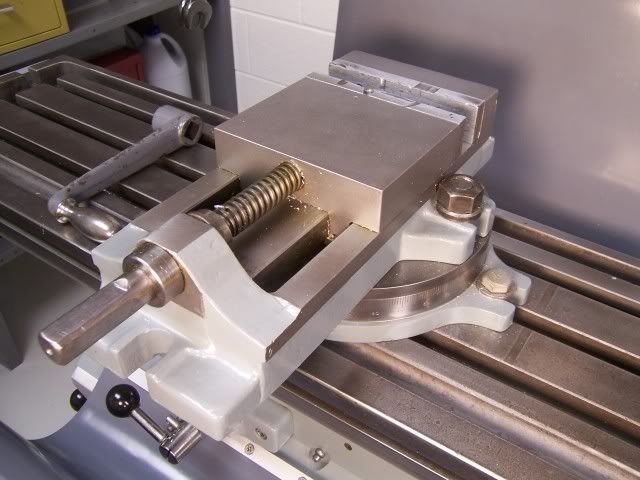
Part way into the project, I got a call saying a vise was found in the previous owner’s effects that might belong to the mill. Lo and behold, it is apparently the original vise that came with the machine. That made my week! I cleaned it up and painted it but still need to make some new jaw faces.
After painting:
Bertha’s spindle has a NMTB 30 taper, and fortunately she came with some tooling. There was a decent set of end mill holders and a couple shell end mills, which all cleaned up well. I subsequently bought an extra ½” end mill holder to dedicate to my edge finder, and a drill chuck arbor and ¾” drill chuck. I also picked up a cheap set of fly cutters and a selection of cheap end mills. I recycled a cleaning cart into a tool caddy to hold the tooling:

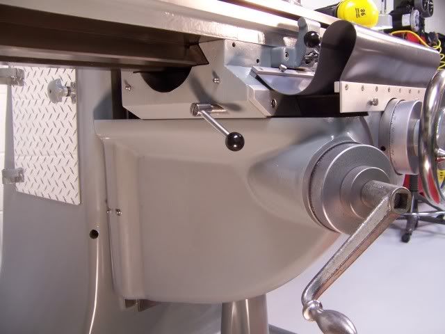
I have had fun with the finishing touches…I got some ¼” felt from McMaster Carr to make new way wipers, and used vinyl shower pan liner to make way protectors. I bolted a 1x1 aluminum bar through the hole where the coolant line used to be to mount lamps and the VFD controls on. The adapter between it and the mill body was made out of maple. I don’t think I’ll be needing coolant for my little projects, but I have the coolant pump if I do need it. 3-phase again, of course. I re-used the original drum switch to control the VFD, and mounted the speed control rheostat next to it. I splurged and bought new knobs for all of the levers (the only plastic on the machine!).
I decided the mill was a little on the low side, so I lagged the base onto some 4x6 sleepers.
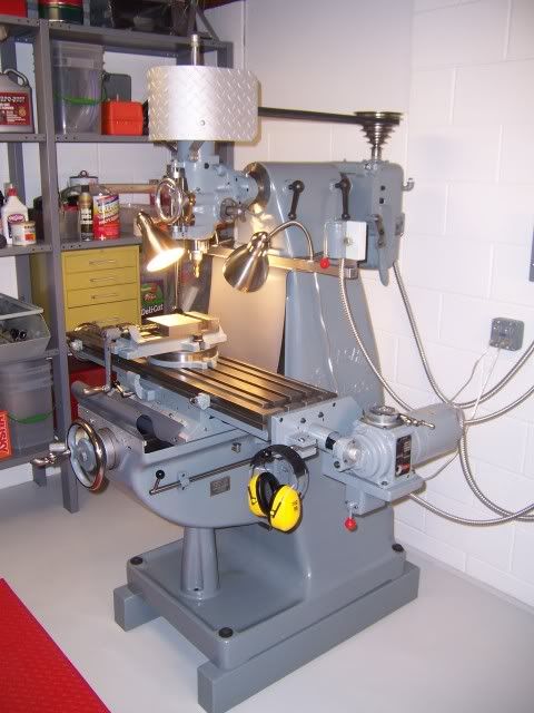
After I got the mill up and running I measured the spindle runout and it seemed excessive. I used a mirror to look up inside the taper and I could see a tiny crescent-shaped ding halfway up where another reform school denizen must have neglected to tighten the drawbar and a tool holder came loose. I glued 1000-grit sandpaper on the taper of one of the holders gave it a spin. The runout is now absolutely minuscule, and I’ve been pleased with the finish on everything that I’ve milled so far. The mill runs super quiet and smooth. I have about $800 in the machine, and she should be good for at least another 60 or 70 years.
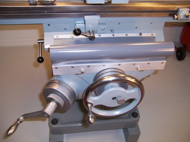
Finished:

That’s about it. I hope you enjoyed my little narrative! The project was very fun and a great learning experience.
The mill is a World War II era machine that was purchased by the Physics Instrument Shop at Duke University. It was eventually replaced by more modern equipment and relegated to the “Staff Shop”, where Physics faculty and students can use the machines to work on their projects. After years of abuse there it was finally deemed surplus and ended up on a trailer parked in the new owner’s yard.
This is Bertha as I first encountered her, having never been unloaded by the previous owner, who passed away shortly after obtaining the mill. Attempts to keep her covered with tarps were futile, and most unpainted surfaces were pretty well rusted. The spindle turned, but not smoothly, suggesting that water had made its way to the bearings.
So, clearly she was in rough shape, but I enjoy a challenge and the price was right ($100). I was able to hitch the trailer to my pickup and anticipated an uneventful drive home of about 5 miles. I had the lathe in the bed of the truck, and the mill weighs about ¾ of a ton, so I was pushing the envelope. As soon as I pulled out on the highway my power brake booster died, rendering the brakes ineffective. I forged ahead, downshifting to slow down for traffic lights, and made it home without killing myself or anyone else. I wanted the machines in the basement of my woodworking shop, which has a grade level pedestrian door in the back but no easy access. I got neighbor guy to drive his little rubber-tracked backhoe over, and with the help of some more neighbors we manhandled the lathe through the door without too much trouble. The mill was much more challenging, as the backhoe wanted to tip over on its nose if the mill was lifted high enough to avoid dragging it. We ended up kind of dragging it down the slope to the door, and set it on some heavy-duty dollies that I had made. I had previously removed the table to allow it to fit through the door, and we horsed it in.
At my leisure, I completely disassembled Bertha with the exception of removing the knee. There were a number of revelations during this process, one of which was that the knee was completely packed full of brass, aluminum, and plastic chips, fused by hardened coolant and oil into an industrial fruitcake-like substance. There had been a pin projecting from the underside of the saddle that had both acted as a travel stop for the saddle and engaged the sliding steel plates that are supposed to keep debris out of the knee. One of the inmates at the reform school must have rammed the pin hard enough to snap it off, which made the sliding plates only semi-functional and periodically allowed a large gap for junk to fall through.
Another revelation was that someone used grease to lubricate all of the zerk fittings on the saddle, table, and knee, rather than way oil, so all of the oil galleys were clogged and there was a nice abrasive paste on all of the ways and a bit of scoring. Some of the pieces after disassembly:
Pulleys, saddle feed screw and handwheel next to Lima drive gear motor (motor already repainted):
Saddle, sliding saddle cover plates, table feed screw:
As feared, water had reached the spindle bearings and corroded them enough to make them unusable. The old bearings were class “0” precision Timkens and no longer manufactured. After much searching I was able to locate a class “3” cone and a standard precision cup from W.C. DuComb Bearing in Detroit to replace the upper bearing. The lower bearing is unobtainable in class “0”, and it appears that the only modern use for that bearing size is in aircraft landing gear. I was able to purchase a Timken cone and cup from Sky Geek in LaGrangeville, NY. They are FAA approved! For those interested, these bearings have a 20629 suffix, indicating that they are specially selected as “prime lot”, honed, and roughly correspond to precision class “2”. I also replaced the two “pulley sleeve” bearings with readily obtainable Nachi components. Total expended on all bearings was about $200.
Spindle receiving new bearings:
The feed screws for the saddle and table were found to be in inexplicably pristine condition after I cleaned the crud off of them. The bronze nuts are adjustable, and I was able to get the backlash down to just a few thousandths on each. I adjusted all of the table, saddle, and knee gibs by trial and error and am very satisfied with the result. The saddle gets a little tighter at the extremes of travel due to wear in the middle of the ways, but it is pretty much irrelevant to me. The bronze bushings for the knee elevation crank were worn into ovals, but they were easily replaced.
Saddle feed screw and knee elevation shaft and bevel gear after clean-up:
The mill has its original motor, which is mated to 4-speed gearbox known as a “Lima drive.” The gearbox had been weeping oil around the shift lever, so I replaced that seal and the motor shaft seals and filled the tranny with Mobil1 gear lube.
The motor is 1 horsepower, 220v 3-phase, and my shop only has 220v single phase power. I am a novice with motors, but I did my research and learned about variable frequency drives (VFDs). It was a 100% no brainer to go with one of these rather than a rotary phase converter. I used a TECO JNEV-201-H1 to power the motor (Dealer’s Industrial Equipment, $131). This is actually a “sensorless vector drive”, which is supposed to maintain full torque regardless of speed. The motor is now variable speed, rendering the Lima drive transmission and step pulleys unnecessary. The tranny can be left in 4th gear and the belt can be left in one position for eternity. This little VFD replaced about 25 pounds of electrical apparatus that had been bolted to the back of the mill.
Bertha also has a power table feed, which has a 1/4 hp 3-phase motor and a bizarre and obsolete variable speed mechanism known as a “ring roller”. There is only one source for the special oil that this mechanism requires, known as “traction lube”, and it is $100 a quart! I did some research, learned that similar technology is used in certain automotive continuously variable transmissions, and the lube for them is only 8 bucks a quart. I bought some, and it seems to work perfectly. To supply 3-phase power to the motor I obtained a ‘last year’s model’ General Electric Model D7206 VFD from Dealer’s Industrial for $31. It is the blue one on the right in the pic above.
Ring roller power table feed:
The mill’s main casting, knee, and head were riddled with chips, and the paint and underlying filler in the coolant pond under the knee were blistered from water pooling there. I bought a cheap needle scaler at Harbor Freight that made quick work of the blisters, and I used Bondo and red oxide putty to fill the defects. The repair sites were primed and the entire casting was then wet-sanded. I sprayed the knee, body, saddle, and misc. other parts with Valspar industrial enamel from Lowes using a $10 spray gun from Harbor Freight. The head and motor were painted using a brush. The access door and the belt guard were too rusty to be worth fooling with, so I made replacements out of aluminum diamond plate.
Most of the rest of the restoration involved de-rusting parts with the help of Evapo-Rust, wire wheels, sandpaper, and glass bead blasting. Anything chuckable, including the solid steel cylindrical ram, was mounted in a lathe and sanded and polished to remove rust and pitting. The 42”-long table was so rusty that I took it outside and lightly sandblasted the top surface, then polished it up with mesh abrasive pads on a hand held grinder. The table, saddle, and knee ways cleaned up pretty well with light polishing with mesh pads.
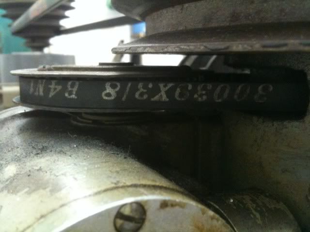
If you look closely at the “before” pics, you will see that there was a power downfeed gizmo that ran off of a timing belt from the spindle. Unfortunately, like so many other aspects of the machine, the timing belt is obsolete and unobtainable. I have found 2 other people in the U.S. who have the same mill, and one was nice enough to take a pic of his timing belt for me. Even with the Uniroyal (now Gates) part number, the engineers at Gates can find no evidence that a belt with that pitch ever existed. I doubt if I will be needing a power downfeed, but I have all of the parts and I suppose I can make new pulleys that will accept a contemporary belt if I need to. The mill has two manual downfeeds--a drill-press-like lever on the left side of the head and a fine downfeed handwheel on the front. These are selected by engaging or disengaging a clutch via a knob on the right side of the head. The fine downfeed is sweet--I can turn the handwheel with one finger.
Part way into the project, I got a call saying a vise was found in the previous owner’s effects that might belong to the mill. Lo and behold, it is apparently the original vise that came with the machine. That made my week! I cleaned it up and painted it but still need to make some new jaw faces.
After painting:
Bertha’s spindle has a NMTB 30 taper, and fortunately she came with some tooling. There was a decent set of end mill holders and a couple shell end mills, which all cleaned up well. I subsequently bought an extra ½” end mill holder to dedicate to my edge finder, and a drill chuck arbor and ¾” drill chuck. I also picked up a cheap set of fly cutters and a selection of cheap end mills. I recycled a cleaning cart into a tool caddy to hold the tooling:
I have had fun with the finishing touches…I got some ¼” felt from McMaster Carr to make new way wipers, and used vinyl shower pan liner to make way protectors. I bolted a 1x1 aluminum bar through the hole where the coolant line used to be to mount lamps and the VFD controls on. The adapter between it and the mill body was made out of maple. I don’t think I’ll be needing coolant for my little projects, but I have the coolant pump if I do need it. 3-phase again, of course. I re-used the original drum switch to control the VFD, and mounted the speed control rheostat next to it. I splurged and bought new knobs for all of the levers (the only plastic on the machine!).
I decided the mill was a little on the low side, so I lagged the base onto some 4x6 sleepers.
After I got the mill up and running I measured the spindle runout and it seemed excessive. I used a mirror to look up inside the taper and I could see a tiny crescent-shaped ding halfway up where another reform school denizen must have neglected to tighten the drawbar and a tool holder came loose. I glued 1000-grit sandpaper on the taper of one of the holders gave it a spin. The runout is now absolutely minuscule, and I’ve been pleased with the finish on everything that I’ve milled so far. The mill runs super quiet and smooth. I have about $800 in the machine, and she should be good for at least another 60 or 70 years.
Finished:
That’s about it. I hope you enjoyed my little narrative! The project was very fun and a great learning experience.
Last edited:

")