Ed:
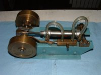
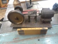
My guess for this engine is that it was not built as a model. It was built with "real work" in mind, and was built in the quickest and easiest way available to the builder. Model engines usually had a bit more detail and finish and were based on typical full-sized engines of similar design. This engine is built solely to run, not to be a scaled down version of some larger engine. The fact there is a pulley with a round groove suggests the engine may well have been intended to drive something like a sewing machine, or possibly it was used to drive ceiling fans.
Lester Bowman references the use of stationary steam engines in New York. In New York City, in the borough of Manhattan, there were many stationary steam engines and steam pumps in use in the older buildings, especially in the old hospitals. Initially, these buildings had their own boiler plants. As time went on, the Consolidated Edison Company (known in NY City as "Con Ed") installed steam mains under the streets of Manhattan and supplied steam as well as electricity to many customers. Newere building were often built without any boilers, and simply used Con Ed-supplied steam for heating and hot water needs. In many of the older buildings, there were steam engines and generators producing direct current, which was quite common in the older in-house generating systems. As the boilers in these older buildings became uneconomical to repair, or the operating costs were weighed against purchased steam, the boilers were shut down. Con Ed supplied steam was used to run the steam engines and other steam driven machinery such as steam elevator hoists, steam pumps for fire and hydraulic elevators, and in a few case, engines for line-shaft drive.
Many of the older buildings in NYC had steam elevator hoists, and looking at old photos of NYC, even in summer, there are plumes of exhaust steam coming off exhaust heads on top of the buildings. These were elevator engine exhausts, and some steam was always bled thru the elevator hoist engines to keep the cylinders warmed and ready to go right into motion.
The last stationary steam engine to run in Manhattan was in a small candy factory. It was a small horizontal engine, and was belted up to lineshafting. The boilers were long gone, and it was being supplied with steam from the Con Ed mains in the street. There was an ancient hospital in lower Manhattan called Gouverneur Hospital. It always had a plume of steam trailing off an exhaust stack on the roof. Gouverneur Hospital had a number of steam engines producing Direct Current, and ran them into the 1970's when the old buildings were shut down. The boiler plant in that hospital had been condemned years earlier, and those engines ran on Con Ed steam for quite some years until the hospital was closed down.
The small engine in this thread looks like it was used for "real work" rather than being built as a model or as a hobby type of steam engine. The use of square nuts and round head screws speaks of something built either out of whatever hardware was at hand. Square nuts on machinery were replaced with hex nuts probably in the late 19th century, but survived a bit longer on things like farm machinery. The cylinder, unless I missed something in the photos, appears to be a solid casting without a jacketing. It looks like the marks of a bastard cut file are still visible on the cylinder body.
The engine's parts are mounted on a piece of plate. I doubt this plate was machined, and I doubt it is really flat. What this means is the engine had to have been built with the fits and clearances of things like the crosshead in the guides, or the crankshaft in the main bearings, on the looser side. It was not meant to be a finely machined engine with close fits, but was something that someone needed for a real purpose. It is too big, given the bore and stroke, to have been a "toy" or "model" engine.
Years ago, before electricity was in common use, ceiling fans in businesses and places like restaurants, hotel lobbies, saloons and similar were driven by round belting such as is used on sewing machines. In cities where there was a constant supply of water from the mains, the ceiling fans were sometimes driven by a "water motor"- a small impulse turbine, or some sort of vane or piston type of machine. Water, being incompressible, does not lend itself to working something like a steam engine, which relies on steam being compressible (and utilizes its expansion). In places where there was no water from the mains, or there was steam in the building, small steam engines were often used to run the ceiling fans.
The engine, assuming the piston is still a reasonably close fit in the cylinder and the slide valve and port face are not too "saddled" (with wear), should run fine on compressed air. A little turbine oil (ISO 46 or 68) in the air going to the engine will help seal things as well as lubricating them. Many times, people have attempted to run things like steam cranes on compressed air and discovered that, while the air is at the same pressure the boiler might have supplied steam at, the steam hoisting engines do not develop the same power. The reason for this is saturated steam ( steam at just the temperature needed to cause water at that pressure to become steam) will contain some condensate (water) once it starts cooling in the steam lines from the boiler. This water acts as a lubricant for the valves and cylinders, and also tends to help seal them. Add the heat of the steam and the resulting expansion of the working parts and the result is a worn engine will always "pull better" on steam than compressed air.
For demonstration purposes, I am sure the engine will run on air, albeit somewhat wheezily, perhaps. A buddy of mine has an ancient horizontal steam engine of 6" bore x 8" stroke. He tried running it on shop air and the thing barely turned over. He then decided to use this vertical firetube boiler that came with the engine. Giving it a quick hydro and inspection, he decided the boiler was OK for lower pressure steaming. He fired it on wood, and was running it on maybe 25-30 psig steam and had it belted to a buzz saw. He was able to buck up cordwood if he took it easy on feeding the wood into the buzz saw. Taking the head off the cylinder, my buddy discovered there was actually some clearance between the piston rings and the cylinder wall, enough clearance to be clearly visible. Despite this, that engine ran on steam and actually pulled the buzz saw. The engine ran somewhat jerkily due to the leakage across the rings, and the exhaust of that engine also told the tale. My buddy asked me to take a look-see. Miking the cylinder, we were surprised to find it was round within about 0.005" top-to-bottom (horizontal engine). The bore did not look bad, no scoring. I took the piston and rod and took a cut on the piston, taking off maybe 0.050" per side (0.100" total cut). I then built up the piston with bronze brazing. My buddy had ordered new rings from Niagara Piston Ring Company, and I re-cut the ring grooves for them. I figured the clearance on the piston a little on the tight side, so my buddy, having his own lathe, skimmed a few thousandths off. His engine now runs so much better, smoother, and the exhaust sounds healthy. The engine now pulls the buzz saw a whole lot better.
Your engine may well have seen some real use, and starting off built to looser fits and clearances, may not run like the proverbial "Swiss Watch", let alone on compressed air. That it will run on air is almost a certainty.
Boilers are a whole other subject of which we've had many discussions on this 'board. Lester Bowman returned a vertical firetube boiler to steam service to run his engines. He had to do an ultrasonic thickness gauging of the boiler barrel and tube sheets, and furnished me with the as-built dimensions, including of the riveted seams. I then ran a set of boiler calculations to determine maximum allowable working pressure. Lester had to retube his boiler as well as equip it with working/new ASME code safety valve, working water level (gauge) glass and try cocks, and with a means of getting feedwater into the boiler. He did a first class job of it and produced a museum quality restoration and the resulting working steam plant is exemplary. Lester went through quite a process to get his boiler from an unknown old boiler barrel to a working boiler fit for steam service. There was no guess work, and we figured things very conservatively.
I am currently in the engineering and project management stages of replacing the original riveted firebox with a welded one on a steam locomotive's boiler. I ran the boiler calculations and filed the Form 4 (boiler registration document) with the US Federal RR Administration on that boiler about 15 years ago. Now, the firebox (original, 1920) is beyond any repair. Too many undocumented repairs, repairs-on-repairs, new cracks... In doing engineering on this sort of job, I found that the ASME boiler codes (Section I, parts PG, PFT, and PW) pretty well provide simple formulas and rules for design of firetube boilers. I also found a wonderful reprint of a text on boiler design" The design of Steam Boilers and Pressure Vessels" by Haven. It is a text from the early 20th century, written by mechanical engineering professors and based on riveted boiler design. It goes a lot further than the ASME code as far as determining things like space needed for "releasing" of steam from the water in a boiler, grate areas, and much more.
I teach a course at Hanford Mills Museum called "Steam Power 101", and aside from the principals and hands-on portions of the course, I do spend a bit of time on boilers and boilermaker's work. A point I make is "Boiler Codes are written in blood". Nowadays, with people having access to MIG welders, one of my fears is that people will think that because they can "lay down a bead" with a MIG welder, they are "real welders". Bad enough when a MIG weld fails for lack of penetration on something like a trailer frame or similar. Far worse if a MIG weld, improperly run, fails on a home-made boiler under steam- maybe fatal. As an engineer who has spent 47 years in the power industry and been around all sorts of welding and related work, as well as being a Certified Welding Inspector, I take a very cautious, if not dim view of most people's ideas of welding, let alone applied to boiler work. Designing a boiler, however small it may be, is something not to be done "by the seat of your pants", or with the idea that a chunk of pipe, some old steel plate and similar can be cut, fit and welded to build a steam boiler.
My 2 cents is to get the engine cleaned up, check the cylinder bore for scoring or excessive wear, and similarly check the slide valve and port face on the cylinder. The port face and slide valve can be brought back to flatness and a good seal by rubbing them against abrasive paper or emery cloth on a flat surface. Finishing with something like 600 grit wet-dry paper wet with penetrating oil (to avoid rusting a flat surface like an iron surface plate or machined table on a miller or table saw) will restore a good steam-tight seal to the slide valve and port face. The cylinder, if scored, could be cleaned up with a hone, and the piston built up with brazing and turned to fit the bore. For running on air, a good close fit on the piston with some small grooves to hold oil would work if the rings are too far gone for re-use.


")