M.B. Naegle
Diamond
- Joined
- Feb 7, 2011
- Location
- Conroe, TX USA
This adventure started over here but I figured a proper thread for this saw would be better (I'll leave those pics there):
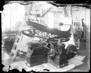
Old horizontal band saws
As I said, I really didn't need another project, but it's here and the desire to see another overhead flat belt machine put back to work beside some modern CNC hardware has "forced" me to start working on this one .
.

It's temporarily outside until I can get some room made under a roof. The first thing I did was dig all of the chips and sludge out of the coolant pan/tank and scrape most of the dried sludge off of the rest of it. I found that they never put a drain plug anywhere on this saw (?) so I drilled and tapped a 3/4" NPT port right at the bottom corner of the tank and left it open so any water can drain out. I've left most of the grime on it and coated everything else with a good rust preventer we have. It sprays on thin and leaves a thick waxy coat behind. I'm trying to take care of it despite the elements.
I did find a serial number located on the front right corner of the table, #824

I also stripped all of the old weld-ment junk off of it, which was mostly stuff to gear down the motor to a manageable speed. The motor was kinda old but had major armature/bearing issues and was really hack-repaired on one side, so It was chunked and I have a couple other options to power it.
I moved the outer shaft bracket back to it's original position and stretched the shaft back out to it's original length. It had a nub on the end so I turned a piece to snuggly fit it, welded them together, and then turned the OD smooth. I had a 12" flat pulley too that I think will work for this application, though I'm still figuring out how to do it.

I did some math and found that to give a range of 50-275 feet per minute (our current band saws range), the input shaft with the 12" pulley will need to turn 33-183 RPM. A 2" motor pulley will be fine for the high speed, and I'm either going to use a 1 1/2HP DC servo motor/controller set we have on the shelf, or an old 1HP 3 phase motor with a VFD, to give the lower speed range. Mounting the motor will be easy as I have plenty of room to put it on a plate under the drive shaft, then I can make a simple enclosure to keep the belt and motor away from chips/coolant.
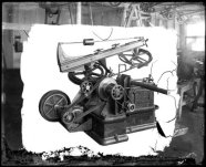
How to mount the 12" pulley is still still up in the air as it originally had a mechanical clutch with it that the operator could engage/disengage as well as having a trip to knock it out when the cut stroke is done. The easy path will be to just mount the pulley solid on the shaft and use a contactor and limit switch to turn on/off the motor. I'm also considering trying to replicate the old mechanical clutch though.
This is another saw with the original clutch.

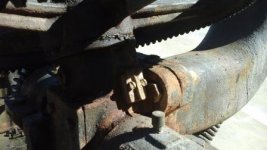
I'm also having to figure out guards for this saw. Originally it had a drip pan that followed the blade around. It think this broken piece is where one end of it mounted.

Old horizontal band saws
As I said, I really didn't need another project, but it's here and the desire to see another overhead flat belt machine put back to work beside some modern CNC hardware has "forced" me to start working on this one
 .
.
It's temporarily outside until I can get some room made under a roof. The first thing I did was dig all of the chips and sludge out of the coolant pan/tank and scrape most of the dried sludge off of the rest of it. I found that they never put a drain plug anywhere on this saw (?) so I drilled and tapped a 3/4" NPT port right at the bottom corner of the tank and left it open so any water can drain out. I've left most of the grime on it and coated everything else with a good rust preventer we have. It sprays on thin and leaves a thick waxy coat behind. I'm trying to take care of it despite the elements.
I did find a serial number located on the front right corner of the table, #824

I also stripped all of the old weld-ment junk off of it, which was mostly stuff to gear down the motor to a manageable speed. The motor was kinda old but had major armature/bearing issues and was really hack-repaired on one side, so It was chunked and I have a couple other options to power it.
I moved the outer shaft bracket back to it's original position and stretched the shaft back out to it's original length. It had a nub on the end so I turned a piece to snuggly fit it, welded them together, and then turned the OD smooth. I had a 12" flat pulley too that I think will work for this application, though I'm still figuring out how to do it.

I did some math and found that to give a range of 50-275 feet per minute (our current band saws range), the input shaft with the 12" pulley will need to turn 33-183 RPM. A 2" motor pulley will be fine for the high speed, and I'm either going to use a 1 1/2HP DC servo motor/controller set we have on the shelf, or an old 1HP 3 phase motor with a VFD, to give the lower speed range. Mounting the motor will be easy as I have plenty of room to put it on a plate under the drive shaft, then I can make a simple enclosure to keep the belt and motor away from chips/coolant.
How to mount the 12" pulley is still still up in the air as it originally had a mechanical clutch with it that the operator could engage/disengage as well as having a trip to knock it out when the cut stroke is done. The easy path will be to just mount the pulley solid on the shaft and use a contactor and limit switch to turn on/off the motor. I'm also considering trying to replicate the old mechanical clutch though.
This is another saw with the original clutch.

I'm also having to figure out guards for this saw. Originally it had a drip pan that followed the blade around. It think this broken piece is where one end of it mounted.


 .
.

