What's new
What's new

New to me Hendey 12x6 - First Lathe

mjmmkerr

Plastic
Joined
Apr 20, 2020
I am new to owning a metal lathe picking up a Hendey Lathe this weekend for $400. It was parked in a barn and hadn't been touched for a while. SN is 23043. It is a 12x6, with a three speed Lima Motor gearbox mounted on it, the motor is 1hp, 440/220V three phase. Having no three phase in my house, I was looking at a VFD from Automation Direct with single phase input and three phase output. It came with a Whiton 4 jaw chuck mounted, no tooling or tool post included. All of the gearing appears to be in good shape from what I have seen so far. I have been reading a lot of the posts on here about these lathes and the lovely Hendyitis which this lathe currently suffers. Evidence points to someone trying to work on the spindle as the collars I and L and gear J were off already and collar E is loose, based on the drawings Johnoder has posted. I was able to remove the chuck, but haven't been able to budge the faceplate currently mounted on the spindle. I am assuming that until the faceplate is off and I remove collar A that I won't be able to remove the spindle. Any sources for appropriate pin spanners? It appears there are no pin holes left on the collars (A and 5) around the front bearing. It also appears that the rear bearing set is babbit and the front bearing set is bronze. I would show pictures but I will wait on those for a bit as I have already maxed this posts attachment limit. Any words of wisdom would be helpful with pulling the faceplate and spindle, and of course with anything else. Thanks in advance!

20200420_195044.jpg20200420_195056.jpg20200420_195101.jpg20200420_195106.jpg20200420_195127.jpg
 
welcome, you have come to the right place for assistance with a Hendey (not particularly from me, though!).

one thing you might be able to clear up is what do you mean when you say you got the chuck off but not the faceplate?

perhaps you mean the "backing plate"? a faceplate is a flat plate with slots or holes to drive a dog, and you would have either a faceplate OR a chuck on a spindle. if you unmounted the front of the chuck from its backing plate (take pics) then you should soak the spindle threads with penetrating oil (pb blaster, liquid wrench) and RE-mount the chuck body, THEN try unscrewing the chuck. you will find many threads on here on that topic, but the place to start is an adjustable wrench on one of the chuck jaws and a mallet.
 
Welcome - good to see digesting of info on the forum - with understanding

Spindle comes out that end - front "brass" doo dad is just a dust cover - if you think about it - it could be unscrewed bit by bit as the spindle headed out (to keep out of the way of the spindle flange). You have to do this to some of the ring nuts anyway.

With the spindle out you then have an opportunity to rig what ever to seriously hold spindle still while you worked on unscrewing chuck back plate
 
perhaps you mean the "backing plate"?
You are correct, back plate. Still working on terminology. I PB blasted the threads last night. When I went to try and unthread the back plate, I was able to get the spindle to turn, unfortunately. It doesn't turn freely, but enough to not assist with the plate removal.

Welcome - good to see digesting of info on the forum - with understanding

Spindle comes out that end - front "brass" doo dad is just a dust cover - if you think about it - it could be unscrewed bit by bit as the spindle headed out (to keep out of the way of the spindle flange). You have to do this to some of the ring nuts anyway.

With the spindle out you then have an opportunity to rig what ever to seriously hold spindle still while you worked on unscrewing chuck back plate

Makes sense. I will see if I can get the cover to move bit by bit.

And don't try to remove the chuck by locking up the back gears, if you do you will probably need to fix the teeth you broke off the gears.

Agreed, I thought about it for about two seconds and figured I would wreck something if I did that. Glad I was on the right track with that. Thanks for the link. I will review that thread as I hadn't seen it yet.
 
I'd give it a gentile nudge before disassembling it, put the front back on, wrench on the jaw, engage back gear, and jam some wood in the gears at the bull gear. I start with cedar because it conforms well, but the idea is it spreads the load over a number of teeth and loads in compression instead of shear. a block of hardwood just the right size added to that. don't go crazy, but it might make things a little easier to take apart if the chuck is off. good luck!
 
Spindle is out

I was able to get the spindle out. Thanks for the guidance there. Back plate is still on, but I'll work on that this weekend. The sleeve that goes over the spindle and through the rear bearing is stuck though. There isn't anything that holds that in place, is there? I'm guessing it is why my spindle isn't freely spinning. Thoughts?
 
I was able to get the spindle out. Thanks for the guidance there. Back plate is still on, but I'll work on that this weekend. The sleeve that goes over the spindle and through the rear bearing is stuck though. There isn't anything that holds that in place, is there? I'm guessing it is why my spindle isn't freely spinning. Thoughts?


Possibly helpful scans posted often before

All parts.jpgList.jpg
 
Just for better clarity from my previous post. Using your diagram, the rear journal sleeve (10) is stuck in the rear bearing (8). All adjusting collars are removed. I am thinking some wood blocks on both sides and a c-clamp may be more persuasive than the deadblow has been so far.

I have questions about the spindle and the cone pulley. See the attached pictures. The bore on the cone pulley appears to have grooves inside of it. Is this normal, for carrying lubrication possibly? The spindle also shows some wear, but the surfaces that show wear don't necessarily appear as journals for bearings. What should I be concerned with as far cleaning up or otherwise? I also took a couple of pictures of the front bearing. Any concerns there from what anyone can see? Thanks.

20200422_222514.jpg20200422_222549.jpg20200422_222632.jpg20200422_222715.jpg20200422_222742.jpg
 
There is normally nothing holding rear conical journal in rear conical bearing except the adjusting collar.

Suggests disregard of lube to the point of welding bearing material to conical journal - and the spindle has not rotated since

As far as cone fit on spindle, one can see this seldom if ever got lube, either. There are cases in the SB section of this forum with cones galled to spindle

Possibly this Hendey was repowered and run way too fast, with no oil can around handy. Here is Hendeyman's thread on speeds - the 12 being a relative speed demon at around 800 tops

https://www.practicalmachinist.com/...-head-spindle-speeds-191988/?highlight=speeds

ph
 
I was able to get the journal out. Took more than a standard c clamp. I ended up using a C press for ball joints. It popped out finally. There is some damage to the end of the bearing along the outer rim, away from the cone pulley. Will this become a bigger issue having a thrust washer against the surface? I would like to end up with a serviceable lathe. Will this bearing need to be replaced?

20200424_232651.jpg
 
Is the ring in there somewhere?

As far as replacing anything, I would imagine the best plan would be to get it all cleaned up so you can see better what you have

It would be quite a project to make either of those bearings with their taper bores and slot for ring etc

A good investment would be to ask hendeyman to send you copies of the drawings for such as that bearing - would give a great idea of the work involved


I was able to get the journal out. Took more than a standard c clamp. I ended up using a C press for ball joints. It popped out finally. There is some damage to the end of the bearing along the outer rim, away from the cone pulley. Will this become a bigger issue having a thrust washer against the surface? I would like to end up with a serviceable lathe. Will this bearing need to be replaced?
 
The ring is present in the rear bearing. Here is a better picture of the damage to the Babbitt. It is on the bottom of the bearing.

I did pull the headstock off and opened up the gearboxes. All of the gearing looks good so far. Haven't touched the apron yet though. All of the single tooth dogs are intact.

20200425_135441.jpg20200425_135423.jpg
 
Yep - the original material tends to crumble away. Such a place could be built up with something like one of the metal based epoxy concoctions (hopefully better than JB Weld) to at least control the oil loss - but to get it to stay put would require all the area to be very clean and no oil present

The ring is present in the rear bearing. Here is a better picture of the damage to the Babbitt. It is on the bottom of the bearing.

I did pull the headstock off and opened up the gearboxes. All of the gearing looks good so far. Haven't touched the apron yet though. All of the single tooth dogs are intact.
 
mjmmkerr:

Hendey lathe No.23043, a 12 x 6 Cone Head model, was built on March 23, 1920. The original owner was the Stromberg Motor Devices Company, Chicago, Illinois. At a later date it was sold to the Sullivan Machine Shop, Goshen, Indiana. This lathe is a 1918 design model. There are no longer any Patterns, Castings or Repair Parts left in inventory for this lathe. All of the original drawings are still in the files, so parts can be made if required.

I will take a look at the Bearing drawings tomorrow and give you a few suggestions for servicing the
Headstock. Short of making a new rear Bearing, I agree with John Oder that an epoxy filler might be the
easiest repair. Unless it didn't show in your photograph, I didn't see the oil return hole in the front
Bearing shell. Also, do you have both of your Oiling Rings?

Hendeyman
 
I always like to see Hendeyman's reply to a query. Like a look back.

"Your mother-in-law was pulled over for reckless driving in 1938 - and while breathalyzer tests did not exist, she did agree to a charge of "impaired driving" and paid the fine. The records were expunged in 1998 when the legal record went 'digital' and the county in cost savings deleted records older than 40 years."

Keep up the good work. One of the challenges of humanity is to preserve what our ancestors knew as "common knowledge." Many today don't even know a challenge exists.

"When someone dies a library closes." Hendeyman is keeping the door open a while longer.

Joe in NH
 
mjmmkerr:

Hendey lathe No.23043, a 12 x 6 Cone Head model, was built on March 23, 1920. The original owner was the Stromberg Motor Devices Company, Chicago, Illinois. At a later date it was sold to the Sullivan Machine Shop, Goshen, Indiana. This lathe is a 1918 design model. There are no longer any Patterns, Castings or Repair Parts left in inventory for this lathe. All of the original drawings are still in the files, so parts can be made if required.

I will take a look at the Bearing drawings tomorrow and give you a few suggestions for servicing the
Headstock. Short of making a new rear Bearing, I agree with John Oder that an epoxy filler might be the
easiest repair. Unless it didn't show in your photograph, I didn't see the oil return hole in the front
Bearing shell. Also, do you have both of your Oiling Rings?

Hendeyman

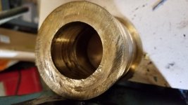
Since you mentioned it, there appears to be no oil return hole in the front bearing, nothing like what is in the rear bearing with grooves and the holes. I am wondering if the front bearing was replaced at some point. I noticed that the oiling ring on the front bearing is nothing like the oiling ring on the rear bearing. The front is more like a piece of thick gauge wire and not a complete ring. It is thinner than the rear bearing oiling ring as well. I don't have pictures of it, but can get some tonight and I will reverify the oil return hole for the front bearing. Do you recommend removing the rear bearing at this point, or better off leaving it alone since it is already crumbling and repair in place? Drawings would definitely help with the front bearing to verify that it is to spec. I appreciate the history on the machine. Pretty cool information. I agree with Joe and the preservation of the historical common knowledge!

Thanks.

Matt
 
So I finally got back to post some more pictures. Here is a picture of the oil ring from the front bearing.

20200429_205101.jpg

Also a couple of clarifying pictures of the front bearing based on Hendeyman's question about the oil return hole missing.

20200429_205035.jpg20200429_205037.jpg20200429_205045.jpg20200429_205050.jpg
 
I have also started stipping the paint off. Bit by bit.

20200503_220656.jpg

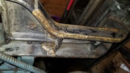
I was curious about what appears to be welding material or filler on the motor mount. Any thoughts on what they may have used to weld the flat stock to the side of the cast iron?

20200503_220750.jpg20200503_220755.jpg


Back
Top