What's new
What's new

Newbie Acquires Hendey Cone Head Lathe

fa_ember

Plastic
Joined
Sep 24, 2019
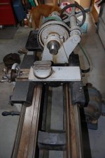
Greetings all. This is my first post here. I'm a woodworker who, in the process of restoring my old woodworking machines, realized how useful a metal lathe could be for various shop needs. I don't have experience with a metal lathe, and this Hendey is my first. I welcome any helpful information regarding the history of this lathe, including date of manufacture, etc., along with any advice and insight about getting it operational and using it. I have come across the one Hendey manual here for the tie-bar lathes, and I assume it will be closely applicable to mine.

The serial number in the bed of mine is 1750. In searching this site, I've never come across a Hendey lathe serial number that low before, so I'm wondering if there is even any information about this lathe. Hopefully hendeyman will come along and offer some information, as I understand he often does.

I know there are a two or three gears in the gearbox that have broken teeth, along with a broken tooth on the manual carriage advance gear, so I will be looking into how to repair those. Also, the gears on the outside of the headstock end were disassembled before transport by someone else, so I need to figure out how those go back on. I was told that this lathe has a plain tool rest that does not turn (is not "compound") and would like very much to figure out if that is, in fact, true, and if so, how much of a handicap that will be, or how can I change it to a compound tool rest.

One obviously critical thing I must do before I can begin using the lathe is to design and fabricate a countershaft assembly along with a matching stepped cone pulley, as I assume there's no chance of finding a Hendey motor drive system in "the wild." Advice and ideas on that are most welcome, too. I have acquired a Diehl 2 HP 3-phase motor that runs at 830 RPM and planned to use it with a VFD to drive the lathe.

Here are some photos:
 

Attachments

  • Hendey_cone_head_lathe_front_view_20190925_112515.jpg
    Hendey_cone_head_lathe_front_view_20190925_112515.jpg
    91.9 KB · Views: 368
  • Hendey_cone_head_lathe_serial_20190924_195932.jpg
    Hendey_cone_head_lathe_serial_20190924_195932.jpg
    102 KB · Views: 213
  • DSC_8014.jpg
    DSC_8014.jpg
    90.6 KB · Views: 237
  • DSC_8016.jpg
    DSC_8016.jpg
    88.3 KB · Views: 309
  • DSC_8019_rotated.jpg
    DSC_8019_rotated.jpg
    91.9 KB · Views: 223

Attachments

  • P1010011sm.jpg
    P1010011sm.jpg
    89.5 KB · Views: 147
  • P1010010sm.jpg
    P1010010sm.jpg
    89.1 KB · Views: 136
  • P1010007sm.jpg
    P1010007sm.jpg
    92.9 KB · Views: 174
  • P1010006sm.jpg
    P1010006sm.jpg
    90.9 KB · Views: 153
  • P1010005sm.jpg
    P1010005sm.jpg
    91.2 KB · Views: 153
fa_ember:

No information is listed for Hendey Lathe No.1750 other than it is a 14 x 8, no original owner is listed. Production records only go back
to 1899 and so it is necessary to interpolate Serial Numbers to get a circa of manufacture. In this case, late 1894 or early 1895 is about as close as I can come as to when your lathe was built. This Patent 14 inch Engine Lathe was a model M14. All of the original drawings are still in the files, so parts can be made as required. In fact, while I am typing this post, I have the original February 1, 1893 drawing of all the gears used in your Norton Gear Box and any of the Change Gears that were used with the seven threads per inch
Leadscrew. A standard set of Change Gears should consist of the following gears: (2) 36T, (1) 38T, (1) 69T, (1) 72T and (1) 144T. All
references on the Index Plate to "STUD" are to be put on the Sleeve Gear shaft. The term "SCREW" refers to the input shaft on the Norton
Gear Box. Used the other Gears as "IDLERS" on the sector. The gear train starting at the Spindle will be the Spindle Gear, the Inter-
mediate Gear and the Sleeve Gear. If you decide that you want to have some gears made, let me know, I give "group" rates when I have to
make several gears.

The Plain Rest was standard with all lathes, at this time, with one of three choices include in the purchase price. The most popular tool
Post was the Compound, followed by the Homan Tool Post. The other was the Quick Elevating Tool Post. Keep in mind that any Compound Rest
built prior to 1904 will fit your lathe and the chances are good that any built up until 1914 should fit.

The Countershaft drawings for your lathe are the No.44 Series. If you need a set, I can have a blueprint company run off a copy.

Hendeyman
 
I appreciate all the responses and helpful information. I was looking forward to learning exactly when this was made and for whom, simply because that adds interest and a back-story, but conversely, knowing that this is such an early specimen adds interest for me in itself. Restoring this lathe would be very rewarding for me, but the apparent lack of documentation for this era (manual, diagrams, and other folks' documented repairs) makes me a bit apprehensive. It seems there is a fair amount of information available for the 1920s era tie-bar lathes, but from what I understand from recent reading, there were some significant changes between my 1894 lathe and the 1920s lathes, i.e. tapered spindle bearings and changes to the apron configuration.

Still, I hope to be able to proceed, though I know it will be a fairly long-term project for me. I need to fabricate a motor drive system with countershaft (presumably after designing one) -- Hendeyman, I plan to contact you for more info about acquiring the countershaft drawings. I have several gears that have broken teeth, though I don't know how critical it is to fix all of them--things seem to turn alright as it, except the longitudinal travel of the carriage. Attached photos show all of the gears with broken teeth except one--the gear for manual longitudinal advancing of the carriage has one broken tooth that definitely needs to be repaired or replaced. I don't know for sure how to evaluate the condition of the spindle other than what was obvious to me--putting a board under the spindle nose and trying to pry up to see if there was any slop. There was none, and the spindle turns smoothly.

There are so many things on the "to-do" list for this lathe, I don't really know where to begin. I could try to tackle the motor drive system first so that I could actually get the lathe turning under power for the sake of further evaluation and to see if something negative shows up that would only manifest under power. Alternatively, I could jump right in and begin disassembly, cleaning, & repair of gear teeth and whatever else I discover as I go, saving the drive system for later.

I will mention that this leadscrew is 6 threads per inch, by the way. I don't know if that changes the list of Change Gears it should have. It came to me with (1) 24T, (2) 36T, (1) 69T, (1) 96T, & (1) 144T. I had no clue how the Change Gears should be arranged until Hendeyman explained the "SCREW" and "STUD" positions. Putting that together with the Index Plate info helped me figure that out. If I am in fact missing (1) 38T & (1) 72T gear, I wonder how important it would be to have them if I'm only doing hobbyist work.

Again, thanks for all the responses, and I will appreciate any continued assistance and advice anyone can offer in regard to these questions and future ones.


Change Gear arrangement & tooth count:
DSC_8028_change_gears_annotated.jpg

Missing gear teeth in Quick Change Gear Box:
DSC_8025_QCGB_cropped_annotated.jpg

Missing tooth on spindle gear & obstructed gear movement:
DSC_8031_missing_tooth_small_spindle_gear_annotated.jpg

Index Plate:
DSC_8027.jpg
 
Easy to see from photo #1 and #4 that it is set up for 11 1/2 TPI - certain sizes of pipe threads

The math is as follows

69 / 36 = 1.9166666 to 1

lead screw pitch .1666666" divided by 1.916666 = .087", the lead for 11 1/2 TPI

The 144 has no function except as an idler

If you removed the 69 and replaced it with the unused 36 you would be set up for 6 TPI
 
Check on eBay for parts. There is usually a lathe or two being parted out. I see at least one right now (12") that might have some parts that will interchange. You'll need to check carefully but I do see some gears that I think will fit. You'll need to ask Hendeyman about fitment, but there is a crosslide and compound up there right now.
 
fa_ember:

Because the Intermediate Gear does not use a detent to keep it engaged, most people assume that some sort of bushing is required to keep
it engaged. Since the Spindle only rotates in one direction, the natural tendency is for the gear to stay engaged. When the gear is moved
toward the Headstock and disengaged, it remains disengaged. To aid the gear in remaining engaged, the Intermediate Gear Stud is ground with a slight taper at the end of the stud. The slight taper is not noticeable and unless you have the drawing in front of you, you would never suspect it was there in the first place. That's the secret to keeping the Intermediate Gear in mesh without a detent.

Hendeyman
 
Check on eBay for parts. There is usually a lathe or two being parted out. I see at least one right now (12") that might have some parts that will interchange. You'll need to check carefully but I do see some gears that I think will fit. You'll need to ask Hendeyman about fitment, but there is a crosslide and compound up there right now.

RCPDesigns, thanks for the tip. I noticed those parts on eBay, particularly the compound rest. 1) Hendeyman said any compound made up to 1904 and probably up to 1914 would work on mine. I have no idea how to determine if that compound rest would fit mine. I asked the seller to provide more than one photo (even though I still wouldn't know how to determine fitment), but that request was met with nothingness. 2) I haven't been in the market for anything quite like this before, so I don't have a point of reference, but the asking price seemed awfully rich to me. If that's a typical market rate, so be it, but it's likely out of my range.

As much as I would prefer to have a Hendey compound on my Hendey lathe, price may prevent it. I have a compound of unknown [to me] manufacturer that was given to me; I may see if there is a way I can adapt it to work on my cross slide before shelling out a couple hundred for a Hendey compound that may or may not fit my machine. Photos of the compound I have:

20191008_191351.jpg

20191008_191405.jpg

20191008_191428.jpg


fa_ember:

Because the Intermediate Gear does not use a detent to keep it engaged, most people assume that some sort of bushing is required to keep
it engaged. Since the Spindle only rotates in one direction, the natural tendency is for the gear to stay engaged. When the gear is moved
toward the Headstock and disengaged, it remains disengaged. To aid the gear in remaining engaged, the Intermediate Gear Stud is ground with a slight taper at the end of the stud. The slight taper is not noticeable and unless you have the drawing in front of you, you would never suspect it was there in the first place. That's the secret to keeping the Intermediate Gear in mesh without a detent.

Hendeyman

Are you possibly suggesting that the bushing that is on mine and preventing that gear from moving toward the headstock and disengaging may be something put there by a previous owner... and doesn't belong? I removed the stud to have a closer look. The bushing is on tight. Should I try to remove it or does it belong there?

20191008_185838.jpg

Another question I have is about the tailstock. Turning the crank COUNTERclockwise advances the quill, clockwise retracts it. That seems counter-intuitive to me. Is that the way Hendey made them, or might something be wrong?

VIDEO: [video]http://networthyinc.com/personal/OWWM/1894_Hendey_14_lathe/20191008_181243.mp4[/video]
 
Turning the crank COUNTERclockwise advances the quill, clockwise retracts it. That seems counter-intuitive to me. Is that the way Hendey made them, or might something be wrong?

Has RH screw and nut fitted. Hendey (and all lathes I have been around for over 60 years) have LH screw and nut
 
fa_ember:

Regarding the Intermediate Gear Bushing, the Bushing and the Gear are one sliding unit with the Bushing extending to the left of the Gear
forming a knob for sliding the gear in and out of engagement. Any other Bushings on the Intermediate Gear Stud doesn't belong there and
should be removed.

John Oder is correct, when your lathe was built the standard Tailstock Spindle Screw was cut with a Left Hand Thread. In your case the
Nut is 1-1/2 inches long by 1 inch in diameter and is threaded 5/8 inches in diameter by 8 Square Threads per inch. I have no explanation
why anyone would go to the trouble to change the Spindle Screw and Nut from Left Hand to Right Hand.

Hendeyman
 
When you get the lathe going make sure you oil it often and have a good supply going to the headstock bearings. Don't take this wrong, but some of the woodworkers I know don't like oil too much. There is probably a lot of oil holes hidden or plugged with a screw all over the lathe.
 
fa_ember:
Regarding the Intermediate Gear Bushing, the Bushing and the Gear are one sliding unit with the Bushing extending to the left of the Gear
forming a knob for sliding the gear in and out of engagement. Any other Bushings on the Intermediate Gear Stud doesn't belong there and
should be removed.

I got the offending bushing removed and the stud reinstalled. Small victory... hopefully one of many to follow. I'm sure glad you told me about the slight taper. It would've made pulling off the bushing an unenjoyable experience if I had tried to pull it off the larger end.

John Oder is correct, when your lathe was built the standard Tailstock Spindle Screw was cut with a Left Hand Thread. In your case the
Nut is 1-1/2 inches long by 1 inch in diameter and is threaded 5/8 inches in diameter by 8 Square Threads per inch. I have no explanation
why anyone would go to the trouble to change the Spindle Screw and Nut from Left Hand to Right Hand.
Hendeyman

Someone offered me a guess as to what may have happened with the tailstock. I just learned about Hendey-Morse tapers, so a friend suggested that maybe a previous owner wanted to change the tailstock spindle to a standard taper, but didn't have the skill, resources, or knowledge to make or get a LH threaded tailstock screw. I put a MT2 taper into the existing spindle/quill and it had a tight fit. So, this is as good of a guess as I can think of. I don't like the backward functionality, so I'd like to change it. What would be some recommended ways to do this? Will it require having a screw and spindle custom made? Will it have to be a Hendey, or are these parts ever the same between different lathes? How in tarnation does one remove the tailstock cap (i.e. get a grip on it)? Is it RH thread? I don't know what "nut" you are refering to above, Hendeyman, but maybe it will become apparent if I can get the tailstock disassembled.

Speaking of Hendey-Morse taper, I found a reference table for the measurements of many different standard tapers, but I cannot find a table of measurements for the Hendey-Morse taper. Can someone point me to that information, please? It's not a secret is it? I assume I'm going to have to get/make a bushing to convert the spindle to a standard taper so I can use it.

When you get the lathe going make sure you oil it often and have a good supply going to the headstock bearings. Don't take this wrong, but some of the woodworkers I know don't like oil too much. There is probably a lot of oil holes hidden or plugged with a screw all over the lathe.

No offense taken. Actually, a previous owner of this lathe used it for turning wood, so there is sawdust in places that should never see sawdust. Speaking of oiling, I have no idea what kind of oil should be used on the different places of a lathe. I've heard of "way oil" but am not familiar with it. I presume it's just for the ways, though, so what should everything else be lubricated with?

I'm grateful for all the help.
 
fa_ember:
In your case the
Nut is 1-1/2 inches long by 1 inch in diameter and is threaded 5/8 inches in diameter by 8 Square Threads per inch.
Hendeyman

During the three days it took for my previous post to get approved and show up, I made a little progress. I figured out that the tailstock crank (not an original Hendey hand wheel) pulls straight off of the spindle screw, allowing the spindle screw to come out the other end of the tailstock. So, it appears I don't really need to remove the tailstock cap. I'm curious how anyone ever removes it when necessary, but it seems it's unnecessary for me right now.
tailstock_spindle_screw_2_not_original.jpg

tailstock_spindle_screw_not_original.jpg

tailstock_spindle_not_original.jpg

The spindle and screw are certainly not original. See photos. The screw has RH plain threads, not LH, ACME threads. Someone used a socket head screw in the end of it to make it long enough to push out the MT2 device when appropriate. I would like to change this to LH threaded ACME like it should be. I wonder what the best strategy would be for this... trying to find the used Hendey parts or having the parts made? If I look for used Hendey parts, I wonder if the screw and spindle have to come from a 14" or can be from other sizes. Also, does anyone know what date range would still fit mine?

What is the "nut" that Hendeyman is referring to in above quote?

I still have the other questions in my previous post. Namely:

1. Where can I find a reference chart that shows all the relevant measurements (large end, small end, taper per inch) of Hendey-Morse tapers?

2. What are the recommended options for being able to use a standard taper in the spindle? I assume my spindle has a 4½ HMT because what I believe to be a MT4 shank gets pinched at the small end and leaves a gap around the big end.

3. Is "way oil" the only oil I need to lubricate everything on the lathe? If not, what other kind of oil should I use, and where?

I'm grateful for the ongoing help.
 
Last edited:
fa_ember:

I will try to answer your questions in the order they were posted.

If you will look at the end of your Tailstock Spindle you will see what looks like a bushing, this is the Spindle Nut. It is slid into
the end of the Spindle and retained with a screw in the small counterbored hole in the Spindle and the Nut. It would appear that the new
Nut was not counterbored for the retaining screw. If you can't remove it by driving it out from the front of the Spindle, then set it up
and bore it out. As I mentioned in my previous post, the Nut is tapped 5/8 x 8 LH ACME and requires a special tap, one of Hendey's way
of making a proprietary thread. Since I have the taps, you can make the Nut and send it to me for tapping or I can make the Nut for you.
You can make the Spindle screw according to the drawing and use the Nut as a gauge to get the final fit. The 1894 drawing shows the taper
as a No.2 Morse, but above that is inked in the word Hendey. Until 1903, all literature lists the taper as Morse No.2. I will have to do
a bit of research as to when the charge was made. Also, on later machines, they used the 2-1/2 Morse Taper.

Sometime ago, I posted the dimensions for the Hendey-Morse Taper, but I don't remember the date, maybe a search of the archives will find
something. If you can't find the information, let me know and I can have the blueprint company make a copy of the drawing.

It would appear that the Headstock Taper in the early years was either a Morse No.4 or a Morse No. 4-1/2, no Hendey-Morse Taper being
used. Using the standard Morse Taper Tables, you should be able to determine the correct taper and then make a Spindle Bushing to take the Tailstock Centers.

I have used ISO GST No.32 Hydraulic Oil in all of the bearings and the Bedways,with good results. Others may recommend the use of several
different oils, such as "way oil" and I have no problem with that. Its all a matter of personal preference with all discussions on the
subject being valid.

Hendeyman
 
Hendeyman & John, thanks once again for the helpful information. Hendeyman, it sounds like there may still be a question as to whether my lathe originally came with a standard MT2 in the tailstock or HMT2. Since the spindle doesn't have threads cut into it, but instead uses the spindle nut, I suppose that means that this spindle could maybe be the original, and a P.O. simply changed the nut and screw. I know that when I put a known MT2 taper device into this spindle, it's a tight fit and grabs well. I wonder if there were external measurement marks on the spindle. Mine only has dents and dings.

Back to exploring and learning, for now.


Back
Top