What's new
What's new

Odd Set true type chuck help

Froneck

Titanium
Joined
Dec 4, 2010
Location
McClure, PA 17059
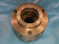
Picked up a set true 8" 3 jaw chuck at HGR a while ago. One piece jaws and don't have the reverse jaw set. Have other chucks, not set true but the jaws on the chuck are correct for what I'm doing. L-0 back plate that looks factory installed.
This set true is not as most set true adjustments are. I have others that fit D1-6 spindle lathe that have 4 flat bottom large diameter set set screws that push against the back plate that has mounting holes larger to allow movement.
This chuck doe not have that type, only 3 adjusters. center of about a 4" long adjuster fits in a hole behind each of the 3 jaws. Adjuster accepts 3/8 hex wrench, has slight taper about 1-1/2 long and threaded 3/8-16
I loosened all 3 (very loose) since the item chucked was running .005TIR out, tightened the one behind the minus jaw and it moved + but it took quite a bit of force on the wrench to turn the adjuster so much force the 3/8" hex wrench would bow. I'm now .0009TIR out, probably good enough. However what am I doing wrong? Back plate is attached with at least 6, probably 8 3/8" flat socket hex head screws and didn't look like it moved. What is the proper way to adjust this type chuck?
 
You have a Pratt Burnerd Griptru chuck. This is an old design from PB that circumvented the Buck patent on their Ajust-Tru chucks. As soon as the Buck patent expired, PB came out with their Setrite line of chucks that are so like the original Buck design that Ajust-Tru and Setrite adapter plates fit each other's chucks.

Meanwhile, the Griptru chucks have to have slightly (hard to say how much) loose screws holding the front and back halves of the chuck together so that the three tapered screws can move the front of the chuck into alignment. Obviously, the two opposing tapered screws need to be backed off when tightening a tapered screw. The screws that hold the adapter plate to the back of the chuck need to be tight.

Here is a video of one being adjusted. How To Adjust a Griptru Lathe Chuck - YouTube

This link includes the PB instruction sheet. Griptru wil not ad just | Model Engineer

I just remembered that I once had a NIB PBI 8" 6-jaw Griptru and still have the pictures of the instructions, so I added them below.

Larry

PBI 8in6jaw 4.JPG PBI 8in6jaw 5.JPG PBI 8in6jaw 1.JPG PBI 8in6jaw 2.JPG PBI 8in6jaw 3.JPG
 
Last edited:
Larry Thanks for the link.I see how the guy adjusted the chuck, yes I managed to get it to .001TIR (slightly less, between the lines of a .001 reading Starrett last word indicator) But turning the adjuster wasn't as easy as shown, bowed a 3/8" Hex wrench with torque needed! (Note I'm using the long legged hex wrench) I also see the chuck was available up to 6" at the time, mine is 8" at least so it was made some time after the article was printed. Not sure but in Fig. 5 thru 8 the chuck and back plate seem to be 3 pieces, mine is only 2 (Chuck and back plate) I'm nor sure how the chuck alters location, something must move but Fig. 2 states push fit for recess so it don't move at that point. I'm thinking I will have to disassemble the chuck after completing the job to see what makes it tick! My chuck is mounted to L0 back plate, assembly looks as it was supplied that way.
Looking at the photos you posted the chuck seems to be 2 pieces and needs a back plate. My chuck is only 2 pieces the L0 spindle mount seems to be machined as part of the second plate in the photo. The attachment screws are the same and there is an additional screw in the holes for mounting the back plate. I'll check but my guess is the back plate with the L0 taper is mounted with 9 screws the same as the 6 in your photo having the additional screws in the mounting screw holes.

Looking at the back plate on my chuck I see I have the 6 screws exactly the same as the chuck without a back plate. As I mentioned my chuck is only 2 pieces (jaws and internal components not included) So I assumed the L0 spindle taper was machined into the second piece by PB. Reading about tightening/loosening the back plate screws as being not required I also assumed that with the 3 piece assembly the 6 screws tightened by PB were covered in addition that some instructed other users to loosen the screws that some users did loosen/tighten the screws when making adjustments. I decided to attempt to loosen the screws, they were very tight! Applying heavy pressure quickly and releasing is a sort of rocking motion loosened the 6 screws which I then re-tightened with torque that did not bow the long length 3/16" hex wrench. When loosened the screw turned with little effort so Loctite was not used. When loosened I was able to use the adjuster and adjust run-out with much lower torque to 0 or so little my .001" graduated indicator did not detect. Small amount of cutting was needed to complete the job, it was removed from the chuck. I might tighten the screws since the jaws were adjusted to 0 run-out so as to avoid any pressure on the adjusters when the chuck is used for jobs not requiring very small run-out of the jaws. Being I have another 8" near new Bison 3 jaw chuck I'll remove it and use the PB for jobs requiring run-out adjustment being that the chuck is in excellent condition. Problem was solved, Thanks for all the Help!!!
 
Last edited:
Just my personal opinion,
but 3 adjusting screws (instead of 4)
would drive me absolutely NUTS.
I would try and re-sell that chuck
so fast, it wouldn't even equalize to
my room temperature. I might even give
it away to someone that I don't like.

-Doozer
 
I agree but I was surprised as to how easy it did adjust. Guy on the YouTube video managed to do it in less time than his long winded introduction. Might have been edited, who knows. However I was able to do it for the first time just as quick! I do have another 3 jaw chuck with D1-6 back plate that is universal/independent. Has the scroll to move all 3 jaws plus each jaw has a screw similar to 4 jaw chuck so adjustment can be made though quite a bit more than than any Set True type, never done it but can true-up a square shaft because jaws have lot of movement available. However it is as you say a pain in the butt to adjust so I usually grab a 4 jaw chuck. In this case I had a rush job, other lathes were set-up, job was small diameter and my 4 jaw chuck for the lathe being used was 11" (actual diameter) PB chuck was sitting there so I used it! Being as it was easy to adjust I'll probably try it again but might regret it!
 
A very informative thread! I have come across those chucks from time to time, and from zero knowledge, passed them up. I would like to try to recondition one of those.
I use these adjustable scroll chucks for parts that are already machined, like for an older hydraulic piston that needs modification for modern seals.
 
I seen a YouTube video a guy made after finding a PB chuck with a back plate added so it becomes a 3 piece chuck and in the link provided by Larry PB claims it's not necessary to loosen the screws holding the middle plate onto the chuck body. This guy removes the back plate that attaches the chuck to his spindle, drills holes in it where the center plate screw are and replaces the screws to the back of the 3rd plate! Pratt Burnerd Griptru 125mm chuck - YouTube
PB states loosening the screws is not necessary while others loosen to make adjustments. I assume PB had a torque setting they used to tighten the screws but someone may have changed it. Not sure what to do.

"Conceptually" I don't like it. But it seems to work OK on collets such as Rubberflex whether I like it or not!

:)

IF.. the real holding power is generated by the friction between two closely fitted plates, AND the screws only serve to generate said friction, AND the force it must resist is a single-point cutting tool. WHICH is intended to fail the metal ahead of its cutting edge, AND NOT grab it like-unto a WRENCH?

The screwed-together plates have significant holding power advantage over the lesser forces generated in the cut.

Or so I SWAG is how it works.

And work it does, so.. "something like that" is surely afoot.
 
I assume if you have only one chuck it might be best to tighten the screws when the run-out adjustment is not needed. Having a Bison chuck the same size not adjustable but in near new condition I'll put the Bison chuck back on the lathe.
 
I assume if you have only one chuck it might be best to tighten the screws when the run-out adjustment is not needed. Having a Bison chuck the same size not adjustable but in near new condition I'll put the Bison chuck back on the lathe.

All my "chucks" have either of the traditional TIGHTLY fitted "spigot" (2-Jaw, 4-jaw, and Walker-Magnetic for Hardinge, UK) ELSE the set-true/tru-adjust hub (a 6-Jaw scroll).

Being old enough to shave even though I choose NOT to do, I do not own any "apprentice chucks", AKA 3-Jaw scrolls. Self-centering NOT_QUITE fully aside, they only produce right about half the GRIP of a 4-J indy.

If I want a part to be set off-center I'd rather decide how MUCH off-center, instead of letting a never-quite NOT off-center scroll chuck take the decision.

:)

It is only amongst my collet systems where there is a "bump to center" back of the sort you describe.
 
I think some of the comments indicate that the design of the Griptru chuck is not comprehended. My post #3 includes the PB cross section drawing and adjustment instructions.

The three tapered screws are used to adjust the work to whatever concentricity is desired. When all three screws are tight, they rigidly connect the front and back halves of the chuck, both radially and axially. The tapered portions of the screws engage partial tapered bores in the front and rear halves of the chuck, making a very secure lock.

The flat head screws keep the front and back of the chuck together when the tapered screws are loose, as they are when making the concentricity adjustment, but otherwise are more or less unloaded when the three tapered screws are tight.

Once an adapter plate is fastened to the rear of the chuck, the flat head screws are covered, so there is no way to loosen and tighten the flat head screws while the chuck is mounted to the adapter plate. The Myford owners have special chucks with the spindle threads cut into the rear of the chuck, leaving the flat head screws exposed. So the Myford owners have to decide whether to change the torque on their flat head screws, causing confusion. Hence that discussion on the UK website I linked.

I bought a new 5" 6-jaw Griptru chuck in London in 1979 and mounted it on a new Hardinge taper adapter plate. I took pictures of it when I sold it years ago. Here they are, to help explain the design.

Larry

Burnerd 5in 6jaw 10.JPG Burnerd 5in 6jaw 11.JPG Burnerd 5in 6jaw 12.JPG Burnerd 5in 6jaw 1.JPG Burnerd 5in 6jaw 3.JPG
 
I think some of the comments indicate that the design of the Griptru chuck is not comprehended. My post #3 includes the PB cross section drawing and adjustment instructions.
Some among us who CAN read drawings unfortunately do not . .when on small-screens, anyway..

:(

Here they are, to help explain the design.

Thank you. Those are SERIOUSLY good at explaining it.

"NOW we 'get it'" "Elegant" concept, even.

And no, there is ZERO relation to how a "bump to center" Rubberflex is mounted.

Mea Culpa. Totally different animals.
 
I can understand not loosening the screws, in the link Larry added much earlier there is quite a bit of information. Seems many don't understand that the screws do not need to be loosened. The guy in the YouTube link I posted drilled the back plate and moved the screws. But in my chuck there is no back plate, the L0 spindle mount is machined into the chuck. My chuck is not like the middle photo, I have only 2 not 3 pieces as shown. Looking at the last photo I do not have 3 screws holding on a back plate. My "Back" plate is the same as the middle plate in the middle photo. It has 6 screws holding it. So the screws are exposed and not covered, I could not move to adjust the run-out unless I applied great force to a long legged Hex wrench. when I did loosen them they too required great force to break them free. So I assume someone thought like the guy in the video loosened them then when re-tightening did so to prevent any movement.


Back
Top