M.B. Naegle
Diamond
- Joined
- Feb 7, 2011
- Location
- Conroe, TX USA
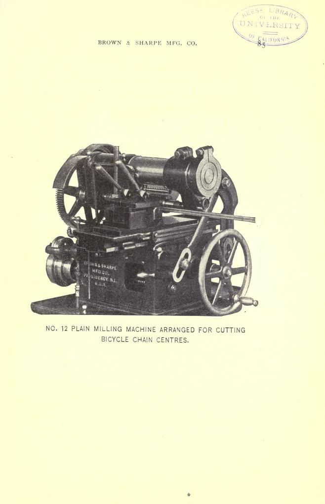
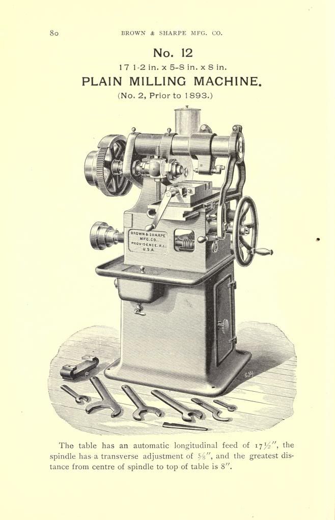
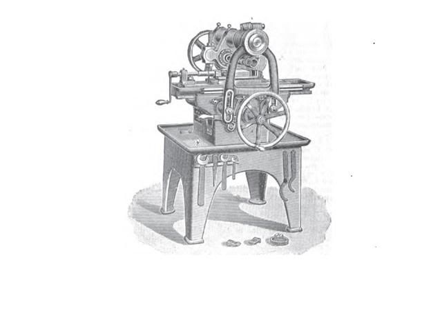
This is a Brown and Sharp Horizontal mill we have at our place. I think this machine's been in service it's whole life. It's seen a few upgrades but I'm thinking about overhauling it someday. I'm wondering if anyone has info on it:
1. In a modern shop, what jobs can this machine do? The machine has No Y movement other than how you space out the cutter. The only jobs I can see this puppy doin is plaining metal with a 6" long or so cutter or doing jobs with a special jig that'll hold your part exactly where it needs to be. The most recent job we've used this machine for was cutting slots with the cutter shimmed to the right space.
2. The Z movement assembly has been replaced. Does anyone have a picture of how this systum originaly functioned? My guess is that it mounted to the spot where we have the feed moter mounted now.
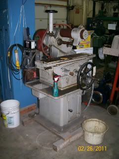
Overall view.
Information
I'm going to redo the motor mount configuration with the motor bolted to the back of the base with the shaft pointing towards the machine.
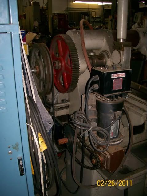
Back view. Obviously the feed motor is aftermarket. There's a pully on the flywheel shaft where I think the Feed motion was originaly taken from. The new system's nice though and will stay (though it might get moved to a more secure location. The control box will be routed to the front of the machine). We also plan to put a good enclosure around the flywheels and belts. Osha will be so pleased.
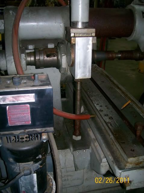
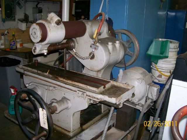
The Z movement I was talking about. The hub that the aluminum block wraps around has incremental lines on it but they're covered up. If I have to fabricate my own systum I'd like to route the handwheel underneith the bed towards the front.
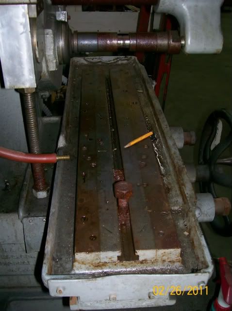
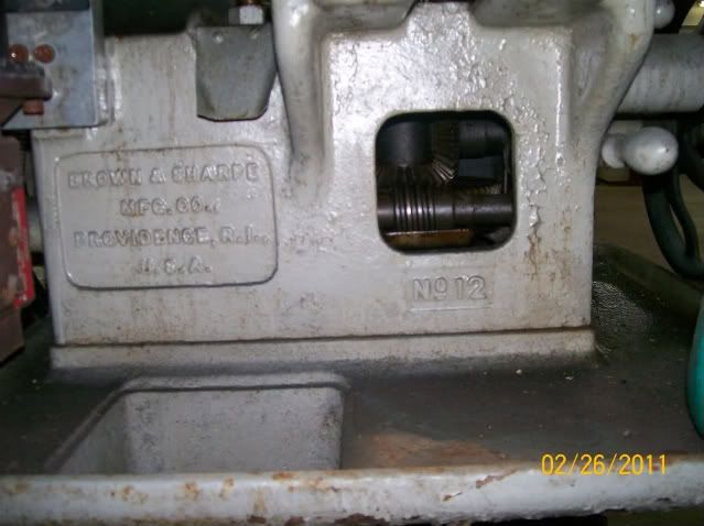
View of the work area. Only a single slot! Lots of machinests didn't like this and put all kinds of threaded holes in the bed. These'll get filled eventually.
1. In a modern shop, what jobs can this machine do? The machine has No Y movement other than how you space out the cutter. The only jobs I can see this puppy doin is plaining metal with a 6" long or so cutter or doing jobs with a special jig that'll hold your part exactly where it needs to be. The most recent job we've used this machine for was cutting slots with the cutter shimmed to the right space.
2. The Z movement assembly has been replaced. Does anyone have a picture of how this systum originaly functioned? My guess is that it mounted to the spot where we have the feed moter mounted now.
Overall view.
Information
I'm going to redo the motor mount configuration with the motor bolted to the back of the base with the shaft pointing towards the machine.
Back view. Obviously the feed motor is aftermarket. There's a pully on the flywheel shaft where I think the Feed motion was originaly taken from. The new system's nice though and will stay (though it might get moved to a more secure location. The control box will be routed to the front of the machine). We also plan to put a good enclosure around the flywheels and belts. Osha will be so pleased.
The Z movement I was talking about. The hub that the aluminum block wraps around has incremental lines on it but they're covered up. If I have to fabricate my own systum I'd like to route the handwheel underneith the bed towards the front.
View of the work area. Only a single slot! Lots of machinests didn't like this and put all kinds of threaded holes in the bed. These'll get filled eventually.
")


 ) and we replaced the spindle center and it's in route to be heat-treated. Found a nice long and narrow vise (good for the tables dimensions). Found out the aftermarket feed motor was dead (still need to tear into it and do a better damage acessment) so at the moment the feed's running off of the main flywheel (original operation) However I found a couple dandy motors in our inventory that I was thinking would make a nice addition. Both are matching variable speed belt drives. There's a 1/2 horse I hope to use for the feed and a 2 horse for the main drive. I'm wondering if the nature of a belt drive variable speed motor will lead to any issues with a horizontal mill? Also would 2 HP be to much for the spindle as it currently has a 1 HP motor? I'm hoping to promote this machine as a hearty metal-mover (we're going to flame-cut and machine a replacement brace for the support arm).
 Just need to make some repairs to the vise, and weld and recut the tang on the arbor. It was twisted and gnarled pretty good but is otherwise stable, It just needs better shape to fit the spindle.