What's new
What's new

Planer Tool Holding - similar to Armstrong 401

matt_isserstedt

Diamond
Joined
Dec 15, 2003
Location
suburbs of Ann Arbor, MI, USA
Sooo

I'm headed down the road of getting the planer going 24x72 table, Putnam. Need some press brake tooling...

I think I want to use a 1/2" toolbit but don't have the proper holder.

I like the Armstrong 401 design but that's basically for a 3/8" sq toolbit.

I can handle designing it to work, but I have a question about the structure.

The Armstrong 401 has a bulbous head on a "flat bar" shaft. I can see why they wanted to conserve material with either a casting or forging.

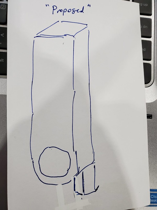
I would propose to make it out of a heavy square bar like 2" square, but to save time bandsawing a bunch of material off, just leave it as 2" square. The planer has a big clapper box and it would easily fit. Not a lantern post with a narrow slow.

Other than the bulk of hefting a big bar around am I making a big mistake in beefing up the structure of it? Seems like the main design element is to get the toobit back underneath the clapper box rather than leading ahead of it.

A couple embarrassingly rough sketches to possibly help illustrate...

General idea behind an Armstrong 401...


My concept....


Thanks as always for your thoughts and comments! :)
 
And there were styles with a small clapper box on the business end - like for doing UNDERNEATH a lathe way. Naturally the main CB would be locked up for such use
 
Armstrong was using the steel efficiently in their design of the planer tool holder. A bit of basic engineering:

The shank of the tool holder is a cantilevered beam. The force applied to the toolbit creates a bending moment in the shank of the toolholder. The toolholder shank has to resist that bending moment. The "property" of a beam section used to calculate how much of a bending moment it can withstand is known as the "Moment of Inertia", being equal to:

I xx = (bd*3)/12 where b = the width of the toolholder shank and d = the depth (or height).

"d" or the height of the rectangular cross section is the key to how much of a bending moment (and how much cutting force) the tool holder can withstand. d is cubed to get the moment of inertia, while "b" is pretty much along for the ride. In short, using a square cross section, while it might be what stock is available, is really not necessary. If the steel in that square cross section could be redistributed (as in a forging operation) to create a rectangular cross section, we would find that a good deal LESS steel is required to carry the same load as a heavier square cross section.

Engineers will recognize that the old familiar "flexure formula" is applied with the moment of inertia, distance to the neutral axis , and using either the allowable bending stress or the developed bending moment, the "beam section" is evaluated. I suppose if a person took the shearing stress for the material being planed, and knew the length of the cutting edge on the toolbit and depth of cut, they could come up with the load on the toolbit needed to take the cut. Working from there, adding in some factor for the impact load seen when the tool first meets the work, one could get a pretty good idea of how husky a tool holder shank needed to be.

Armstrong obviously did the design calculations and came up with toolholders that did the job and lasted through the lifetimes of several generations of machinists and shop owners.

Armstrong was in business to make a profit on the tools they sold. The less steel they used in a tool, the better the chances of making that profit.

I am fairly sure that Armstrong did not forge the toolholders from common mild steel such as A-36 (structural grade) or 1020. Rather, they used some alloy steel with a higher yield and tensile strength. Using forgings, the process created a "grain flow" much like that found in wood. This grain flow in the forged steel gave much better stress distribution, aside from reducing the amount of machining required. Lastly, it is a sure bet that Armstrong heat treated the forgings for those toolholders. Probably normalized the forgings before machining, then normalized after machining followed by an oil quenching and tempering. That oil quenching and tempering allowed the toolholder to stand up to the battering of toolpost screws or clamping hardware without deforming, and also made it a good deal more rigid in terms of "spring" from the cutting force.

Making a tool holder from bar stock is something many of us have done at one time or another. I've used A-36 steel and welded parts together for some toolholders.
Not so pretty as the forged/factory made articles but it does work. I've never made a toolholder to see the kind of service the OP's planer tool holder will be seeing.

Mild steel in its as-delivered condition is "dead soft". As such, in service as a toolholder, some "mushrooming" or deformation of the areas where the clamping hardware bears on the shank would be expectable over time in service. For occasional use, a mild steel toolholder made by hogging it out of bar stock would work, but over time, I think it would come out "the worse for wear" as opposed to "the genuine article" from Armstrong or Williams.
 
Matt,
I like Joe's explanation, a good bit deeper than my knowledge of such but easy to follow. In days gone by I made tool holders to get a particular job done. S-7 at 54-57 Rc seemed to work pretty well but a fat chunk of 1018 would be a poor choice. My 2 cents says if you got a nice vintage Putnam planer then get a few nice vintage tool holders cause together they made trains and ships and tanks and took a pounding but kept on machining.
spaeth
 
I have a whole drawer full of Armstrong lathe tool holders...but only the single 401 and that came with a shaper....and....I used it backwards until realizing recently how it was supposed to be used.

But I don't think the 401 style is available in a 1/2" toolbit. Something tells me I want to use that size. The 4140/42 HT material is going to require slower speeds (thinking 50sfm) and a cobalt steel toolbits, I have several of the MoMax toolbits, pristine. But the heavy toolbit seems like its going to have more thermal inertia when roughing the profile. I think I'll need to grind some radius tools for the bottom and of course the 401 would be a popular finisher.

There's a lot more to the project than that but ya gotta start somewhere :D

Thanks Joe, the economy of materials makes perfect sense, the extra material could almost make another entire toolholder....so I can certainly understand the $ behind that.
 
I seem to recall some discussion about a gooseneck type spring tool holder made by Armstrong or Williams for use on planers made in larger sizes in an older thread on this forum .
They are some times helpful reducing chatter on long and difficult to machine parts and materials.
Her is an example of a smaller I found in an image search from another forum .
They were also used in various forms on lathes and shapers.
Something else to keep an eye open for in used tool holders.
Shaper Tool Holder Question | The Hobby-Machinist.
Maybe someone will remember an example on this forum since any search terms I tried brought no results .
Search link
Armstrong under hung spring type Planer tool holder - Google Search

Some older style planer tools discussed here in this book that I have a printed copy of, if you flip back and forward a few pages from these .
International Library of Technology: A Series of Textbooks for Persons Engaged in the ... : International Textbook Company : Free Download, Borrow, and Streaming : Internet Archive
Regards,
Jim
 
Depending on what you intend to plane I'd get a piece of 1" by 1.25" steel bar about 10" or 12" long and braze a chunk of carbide to the end. Mill out a recess for the carbide. If you're planing cast iron you need a slight negative rake, maybe 4 or 5 degrees.

Regards Tyrone.
 
Digging deep into the dusty way back of memory to dig out a recollection of an hour-or-so conversation with the manager of Armstrong Brothers warehouse in San Francisco . . . He told me that Armstrong used 1050 for both their high-carbon wrenches and their toolholders.

That's definitely "hearsay" that would never stand up in court, so don't take it as written in stone.

Incidentally, I've seen a fair number of DIY versions of swiveling-toolbit toolholders that substituted a short length of axially-drilled round bar (or thick-wall tube) welded across the end of a rectangular bar.

John
 
Probably everyone here knows this, but just in case:

Shaper and planer tool holders made by armstrong have zero back rake built
into them. The tool aligns with the tool holder long axis.

This is unlike the turning tool holders, which have the (square) hole for the tool at an
angle to the toolholder axis, to build in back rake into the assembly.
 
I made something like your first drawing for the shaper. I just turned the round bit, made the bolt and welded it to a decent sized shank I had. Its nice that the cutting tool is back of the shank so when its pushed it lifts out of the cut instead of into it, you can put the tool anywhere you like too.
If its just for one purpose you could braze an appropriate carbide tiped tool behind another shank, you get the cutting edge where you want it, out back.
 
Dave and I worked out a deal, thanks again! For an Armstrong #42 toolholder which is perfect for the 1/2" tool bits....need to make a 1/4" backer as this is expecting a 3/4" thick toolbit.

Some pics of the setup...nice and beefy! I have a 1/4" toolbit clamped in back for the moment.


My hand for scale, this is big stuff.


The scale seems to "fit" just right.


I have some more work to do on the drive system for the table....sort of on hold for a minute due to the global situation trying to conserve funds but the ideas are cemented in my mind :D


Back
Top