What's new
What's new

Post Civil War small Box Bed Steam Engine.

Lester Bowman

Hot Rolled
Joined
Apr 9, 2011
Location
Modesto california USA
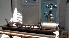
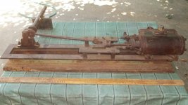
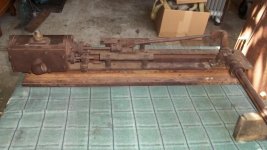
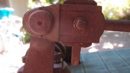
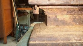
Here are some pictures of an extraordinary small very early steam engine I received from a very good friend ( Thank you Greg!) who also frequents this Forum. It is just a tad under three inch bore by six inch stroke. The bed measures a bit over 36" in length.

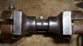
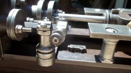
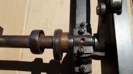
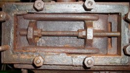
As you can see it has very early features like a cottered rod and cottered connection of rod to crosshead. It has turned pillars beneath the slides and that long stroke crank with the early style "D" valve.Lagging is heavy brass. The threads are not Whitworth nor do they match with any modern pitch.I know our threads are based on Sellers thread but so far I haven't made a determination.

This little guy was found by Greg in Virginia city in a junkyard full of mining equipment. I would think it is probably made in San Francisco,Sacramento or Stockton as all these cities were manufacturing steam engines in that early period. It is not impossible for it to have come around the horn but being unmarked we'll probably never know.
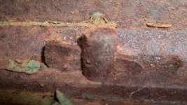
 

Attachments

  • 4280612198.jpg
    4280612198.jpg
    96 KB · Views: 1,492
  • 4280612200.jpg
    4280612200.jpg
    95.5 KB · Views: 1,230
  • 4280612212.jpg
    4280612212.jpg
    96.4 KB · Views: 1,372
  • 4280612206.jpg
    4280612206.jpg
    72.3 KB · Views: 1,099
  • 4280612220.jpg
    4280612220.jpg
    100 KB · Views: 1,051
The cylinder has lugs on one side with bolts going down through into the Box Bed. The other side has a cotter arrangement to draw the cylinder down tight against the bed. There is a outlet beneath the cylinder which I haven't figured out what it does.

This engine came with a very early brass bodied Judson two ball governor which attaches to the steam chest cover. Exhaust appears to come from the top fitting above the cylinder.
 

Attachments

  • 4280612208.jpg
    4280612208.jpg
    80.1 KB · Views: 542
  • 4280612202.jpg
    4280612202.jpg
    49.2 KB · Views: 488
  • 4280612209.jpg
    4280612209.jpg
    96.1 KB · Views: 557
  • 4280612224.jpg
    4280612224.jpg
    77.2 KB · Views: 474
  • 4280612227.jpg
    4280612227.jpg
    98.7 KB · Views: 494
Bottom and top views of cross head. Slide valve. Cylinder head...
 

Attachments

  • 4280612223.jpg
    4280612223.jpg
    101.9 KB · Views: 471
  • 4280612237.jpg
    4280612237.jpg
    96.8 KB · Views: 464
  • 4280612232.jpg
    4280612232.jpg
    99.3 KB · Views: 465
  • 4280612240.jpg
    4280612240.jpg
    101.8 KB · Views: 453
  • 4280612236.jpg
    4280612236.jpg
    96.3 KB · Views: 412
Some other detail views of various parts including a steam chest repair. This engine is missing the flywheel,outboard bearing and the eccentric rod and strap as well as the small end strap and brass on the connecting rod.

However these are all fairly easy fixes and I'm grateful to Greg for allowing me the privilege to acquire and restore this remarkable survivor from the era of steam which has gone mostly undocumented by historians. This little engine will wear its original finish and hopefully as the other parts are made..I can make them look period.

I would be interested in a "S" spoke flywheel about 18 or 20 inches in diameter with an early pattern. I can make the pattern if need be. It is a beautiful little thing and makes me smile even though it is rough and incomplete. It is a miracle it survived.
 

Attachments

  • 4280612215.jpg
    4280612215.jpg
    69.2 KB · Views: 419
  • 4280612217.jpg
    4280612217.jpg
    59.4 KB · Views: 386
  • 4280612244.jpg
    4280612244.jpg
    104.7 KB · Views: 544
  • 4280612207.jpg
    4280612207.jpg
    64.3 KB · Views: 487
  • Broken repaired steam chest pics..Gregs Engine 001.jpg
    Broken repaired steam chest pics..Gregs Engine 001.jpg
    86.3 KB · Views: 463
Interesting that the columns supporting the crosshead guides appear to be different designs, or maybe some were installed inverted during a repair. Nice find and a worthy project.
 
Lester,

From a history point of view, it would be interesting to know if the threads conform to any early standard.

Sixty-degree threads were in use before Sellers 1864 presentation to the Franklin Institute, so that event is not so useful as a milestone in time.

Are you seeing 1/2-12 threads on this baby ?

John Ruth
 
Brian is correct about some of the cross head columns being installed incorrectly. I got all this apart tonight and will post some pictures of it this week end.

John..I was surprised at the thread diameters and pitches. I've been so busy getting it apart I hadn't got that far yet. But I've just finished measuring them and the results are very interesting.

All 60 degree angle..
.262 x 22 tpi...steam chest studs.
.325 x 16 tpi...Bolts holding down the slide bars.
.330 x 20 tpi...Bolts holding cylinder to Box Bed.
.205 x 26 tpi...crosshead top bolts to adjust brasses.
.290 x 22 tpi...cylinder head.
.325 x 18 tpi...Gland side of cylinder head.

I can't make heads or tails of any of these:) I measured the pitch in areas where the thread wasn't "pulled". I am very fortunate most of the hardware is there and usable.

There isn't any bolt larger than .330 diameter. The piston rod is only 7/16 diameter and the connecting rod diameter 5/8" if that.Such a small fragile rod for an engine of nearly three inch bore.

This engine also has a very interesting "ring" arrangement of two split rings diagonally cut slipped over a wide ring with a straight cut..then spring loaded from the inside. I'll post pics after I get it apart.
 

Attachments

  • 4280612281.jpg
    4280612281.jpg
    99.8 KB · Views: 473
  • 4280612249.jpg
    4280612249.jpg
    103.9 KB · Views: 429
  • Gregs Engine..detail shots. Piston,,Cylinder and cross head. 003.jpg
    Gregs Engine..detail shots. Piston,,Cylinder and cross head. 003.jpg
    75.6 KB · Views: 465
  • Gregs Engine..detail shots. Piston,,Cylinder and cross head. 002.jpg
    Gregs Engine..detail shots. Piston,,Cylinder and cross head. 002.jpg
    47.1 KB · Views: 387
  • 4280612236.jpg
    4280612236.jpg
    96.3 KB · Views: 369
Cobwebs in the Cylinder

Seeing the cobwebs in the cylinder reminds me of a half-remembered scene in a long-ago movie. IIRC its in the 1960 version of Exodus.

Here is your list, re-ordered by size, with the closest 64th:

ACTUAL MEASUREMENTS Closest 64th Conjecture
All 60 degree angle..
.205 x 26 tpi...crosshead top bolts to adjust brasses. 13/64 3/16ths
.262 x 22 tpi...steam chest studs. 17/64 1/4
.290 x 22 tpi...cylinder head. 19/64 9/32nds
.325 x 16 tpi...Bolts holding down the slide bars. 21/64 5/16ths
.325 x 18 tpi...Gland side of cylinder head. 21/64 "
.330 x 20 tpi...Bolts holding cylinder to Box Bed. 21/64 "

I cannot see ANY pattern here ! Nada ! The best I can suggest is that EVERYTHING is oversized, and that the real nominal numbers are/were supposed to be even 32nds as listed in the column labeled "Conjecture"

Without any of my older reference books at hand, I cannot find a table of fractional threads smaller than 1/4 inch, but such threads definitely exist - I have two ancient tap & die sets for same. Does anyone have such a table ? If so, what matches ?

I'm wracking my brain to recall any historical pre-Sellers threading system using a 60 degree thread. Please help us out, here, guys ! All you historian types, dive into your Pre-Sellers references and let us know what you find !

John Ruth
 
There really doesn't need to be a pattern, they are what they are. The machinist that made them was probably using a ruler and calipers to make the bolts and maybe his eyesight was not that great. I have run into the same problem on the Otto & Langen engine that I was working on, it is hard to find two bolts that are alike and those are even worse, the thread pitch is neither imperial or metric. Some are 13 2/3 TPI or about 1.9mm pitch. I think the most odd part is the different pitches for bolts that are so close in size, why not just leave the same change gears on the lathe and cut everything from the .290 to the .330 say 18 TPI?
 
Obsolete Units of Measurement

EngineBill,

Whereas Nikolaus Otto and Eugen Langen were Germans, did you check whether the odd TPI might come out "even" in some obsolete, pre-Metric German system of measurement ? Obsolete German units of measurement - Wikipedia, the free encyclopedia

This obviously does not account for variation between bolts on the same machine, but you might be able to figure out what they were theoretically "aiming for".

You are 100% right that there is no reason that an old machine's fasteners must conform to any system at all. However, sometimes it's fun to try to figure out what they were "aiming for".

John Ruth
 
Thanks John,
I didn't realize how convoluted the German systems were. The engine was built in Cologne and their foot was 11.3" long and their inch could have been 1/12th, 1/11th, or 1/10th of a foot. If their inch was 1/11th then the 13 2/3 TPI I measured would equal 14 threads per Cologne inch. The engine was advertised in metric dimensions but they could have been using German lathes or converted English or American lathes, we don't know.
 
Yep. Before certain smart minds cracked down on the mess, Europe used dozens of different thread systems. Some were Whitworth form and pitch, but used the acient system of measurement from the local region for length and diameter.
Others were early proto metric.
Many were completely alien.
 
Thank you for the comments thus far :) These pictures show the piston ring construction. It uses two inner "C" shaped springs pressing the wide inner ring which in turn expands the two outer pinned rings.

I love the picture of the crosshead showing the craftsman's use of scribed lines and dots for reference. It is lovely work.Every piece fits with clock like precision.
 

Attachments

  • 100_3594.jpg
    100_3594.jpg
    85.5 KB · Views: 432
  • 100_3596.jpg
    100_3596.jpg
    58.8 KB · Views: 365
  • 100_3597.jpg
    100_3597.jpg
    54.2 KB · Views: 371
  • 100_3600.jpg
    100_3600.jpg
    51.3 KB · Views: 436
  • 100_3601.jpg
    100_3601.jpg
    69.6 KB · Views: 423
These pictures show the mismatched parts of the existing connecting rod. I will duplicate these for the other end. These are the only parts on the entire engine punch marked..and the marks look very early.

Also construction of the crosshead slides are shown.The little bobbins or columns are shown in their correct position..little flat on bottom so it doesn't overhang the edge of the bed.The slide bars are cast iron as well as the columns.
 

Attachments

  • 100_3602.jpg
    100_3602.jpg
    81.5 KB · Views: 361
  • 100_3603.jpg
    100_3603.jpg
    72.2 KB · Views: 422
  • 100_3606.jpg
    100_3606.jpg
    46.3 KB · Views: 333
Here are a few pictures after most of the cleanup has been done on the parts.The valve chest still needs gaskets.Now I am beginning to think about the outboard bearing and eccentric strap patterns. Plus I need a suitable flywheel plus a few other odds and ends.
 

Attachments

  • 100_3630.jpg
    100_3630.jpg
    84.8 KB · Views: 455
  • 100_3628.jpg
    100_3628.jpg
    59.5 KB · Views: 364
  • 100_3626.jpg
    100_3626.jpg
    77.5 KB · Views: 367
  • 100_3627.jpg
    100_3627.jpg
    74.2 KB · Views: 413
That Governor is a 1/2" Judson. I have already made a new piston rod.I am not quite sure whether I should just copy the main bearing and put it on a riser block or extend it downward so no riser block is needed.

I also need to duplicate the gib and cotter arrangement on the connecting rod..plus straighten it a bit.The crankshaft will polish up nicely. What kind of base should it be mounted too? Ah! All fun!

Now hopefully some of the details will be more apparent and maybe someone has some ideas as to its origin and age :)

Also shown in the first picture is what is left of "something" held on by two screws. It is broken off leaving only a cast iron fragment..any ideas?
 

Attachments

  • 100_3634.jpg
    100_3634.jpg
    75.6 KB · Views: 346
  • 100_3633.jpg
    100_3633.jpg
    62.1 KB · Views: 401
  • 100_3632.jpg
    100_3632.jpg
    72.4 KB · Views: 390
  • 100_3631.jpg
    100_3631.jpg
    77.2 KB · Views: 321
  • 100_3629.jpg
    100_3629.jpg
    81.8 KB · Views: 330
I have seen original governors mounted in the position where the broken bracket is located on the bed, but I'm skeptical it was the original intent of your engine. The two screws don't look adequate enough for a governor. Nice job! Jake


Back
Top