Original Rise & Fall
Thanks Larry.
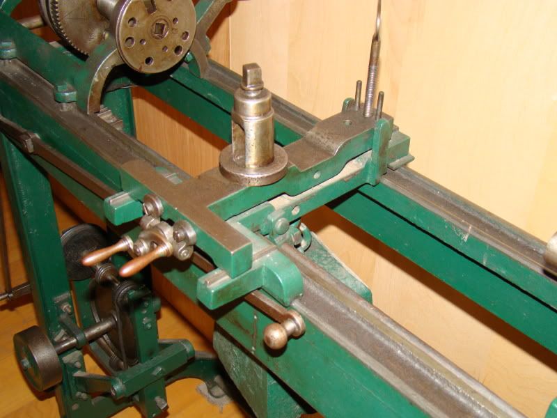
Note this has two radially located "v-slides". A little later version of this lathe would possibly have slider shoes to track the front of the rise & fall element. For all, the rear of the rise & fall element is guided by vertical stops with the elevation controlled by the crank. This is the classic "weighted lathe" of Daniel Wilkinson with three point suspension, which requires a weight to keep the carriage/rise & fall saddle against the shears of the lathe.
Another more recent three point suspension lathe incorporates T-slots along the upper surface of the T-Rise & Fall.
Note also the tool post has its own little stand - which can be moved around the T-slots and placed where needed. Large diameter cuts out on the horns of the "T" are necessarily light, but possible to cut to nearly the maximum swing of the lathe without hindrance by the carriage.
A bit later your Putnam design developed. Some makers/buyers seems to want a full dovetail cross-slide - larger lathes of this ilk tended to go to a dovetail. A separate tool post was probably supplied with the lathe for the few times the maximum diameter capacity of the lathe was needed. This lathe still weighted but because radial tool adjustment was done on the dovetail, the rise & fall part was radially stationary and the rise occurred by pivoting the rise and fall part at the front edge.
But many makers to get away from a cumbersome and heavy hanging weight decided to incorporate a "ball & socket" arrangement on the rise & fall portion elevating screw. The ball and socket would "keep" the rise and fall part solid to the carriage regardless of height setting. And instead makers counted on gibs to hold the carriage to the bed - or simply the combined mass of carriage and apron - or both.
Other makers went with patent "elevating toolposts." A Harris lathe from western Massachusetts was fitted with a "solid" cross-slide but D.L. Harris was a marketer of Chester Van Horn's version of elevating toolpost - which the lathe was absent (those pesky high speed tools remove the necessity and a piece of fine and somewhat intricate mechanism gets left under the workbench in machining expediency.) Here's a pix of the lathe. (Thanks Lester!)
The latest iteration was with the rise of high speed steel in the early 20th century. This obsoleted the need for rise & fall as a machining aid and instead maximized value on a "solid" tool mount. By this time lathes were built with the convenience of a compound slide which while it lost some capacity of the lathe swing over the carriage, increased the ability to turn short tapers, threading, or quick stub machining without moving the carriage laterally.
The transition to high speed steel was not absolute or immediate. Machinists tend to be traditionalists and Pratt & Whitney continued "weighted" lathes almost to and possibly into the 20th century - marketed as "toolmaker" lathes because of their repeatability and accuracy. Which the weighted aspect excels.
As the 1880 census reported on all these developments.
http://www.practicalmachinist.com/v...0Machinery%20used%20in%20Manufactures&f=false
Joe in NH


")