What's new
What's new

Richards Electrabore - Stiff Spindle Problem

Herc D

Plastic
Joined
Jan 25, 2021
Hi All

I've been lurking & viewing for quite some time & apologise that my first post is for help.

We have a Richards ‘Electrabore, Horizontal Borer, Patent Type’, circa 1955 that the traversing spindle has become quite stiff to hand wind in & out. According to the operator it’s been getting gradually worse for some time but has recently become noticeably stiffer.

After a bit of checking the ‘easy to get at’ items I’m pretty sure it’s not the traversing spindle transfer gearbox or the rack & pinion in the aft spindle housing as this appears to be quite free, so I’m thinking it is something within the main head or spindle tube that has either run dry (possible blocked oil feed?) or a bearing picked up in some way.

So I’m thinking of withdrawing the spindle to get a better idea of the issue.
Has anyone had this issue before & does anyone know of a procedure for removing the spindle from the machine without a full dismantle of the main head gearbox?
We have some old drawings, but these are photocopies at A3 paper size & aren’t that easy to read the detail.

I’ve attached a photo for reference.

Thanks in advance.

ATTACH=CONFIG]311542[/ATTACH]
 

Attachments

  • IMG_3206.jpg
    IMG_3206.jpg
    94 KB · Views: 101
Hi All

I've been lurking & viewing for quite some time & apologise that my first post is for help.

We have a Richards ‘Electrabore, Horizontal Borer, Patent Type’, circa 1955 that the traversing spindle has become quite stiff to hand wind in & out. According to the operator it’s been getting gradually worse for some time but has recently become noticeably stiffer.

After a bit of checking the ‘easy to get at’ items I’m pretty sure it’s not the traversing spindle transfer gearbox or the rack & pinion in the aft spindle housing as this appears to be quite free, so I’m thinking it is something within the main head or spindle tube that has either run dry (possible blocked oil feed?) or a bearing picked up in some way.

So I’m thinking of withdrawing the spindle to get a better idea of the issue.
Has anyone had this issue before & does anyone know of a procedure for removing the spindle from the machine without a full dismantle of the main head gearbox?
We have some old drawings, but these are photocopies at A3 paper size & aren’t that easy to read the detail.

I’ve attached a photo for reference.

Thanks in advance.

ATTACH=CONFIG]311542[/ATTACH]

I've worked on these machines in the past but it must be 30 years ago now. The travelling spindle runs inside sleeve bearings that are inside the boring spindle. I've had them all out in the past but as I say it's a very long while ago. That's a pretty early " Electrobore ", probably a late 1940's design of machine. I'm more familiar with the later " Electrobores ", that came out in the early 1960's. They had " Timken " spindle bearings. Your machine will have plain phosphor bronze bearings. The boring spindle has a big double taper bearing that you can adjust from outside the machine but you probably know that already. I'd release the travelling spindle from it's housing on the tail bracket and see if you can move it manually. Try barring it in and out.

If the spindle has to come out it's a relatively simple job once it's been released at the tail bracket end. It should slide out but be sure to support the spindle with a crane etc. If you do remove the spindle be sure to mark up the orientation of the travelling spindle to the boring spindle.

Where abouts are you in the UK ?

Regards Tyrone.

Hi Tyrone

Thank you for your reply & info, I’m in Dartmouth, Devon.
I understand that the machine was originally at Plymouth dockyard before it came to us & rechecking the plate on the side it’s marked 1951, so is definitely getting on a bit.

I’ve released the traveling spindle from its housing in the tail bracket (a square drive accessed via slots in the top) & tried to ‘bar’ the spindle in/out but it won’t budge. I’m guessing I’m going to have to rig up a block to pull it out from the front while supporting it with the overhead crane.

Before I do, is it worth adjusting the spindle bearings (through the hatch in the side of the main housing) or is this adjustment only for axial adjustment & not sliding?
Also for removing the spindle, is it just a case of withdrawing it from the machine, or (apart from supporting it’s weight) is there any other preparation that needs to be carried out or items removed?

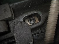
The little window on the side of the spindle frame is solely for adjusting the main bearing for the facing slide ( Boring head, Chuck, whatever you want to call it - facing slide is the correct term ) spindle. If you look inside the window you will see a square socket. That winds the worm that revolves the locking ring around. That pulls the spindle back into a big double tapered Phosphor bronze bearing. There's a shallow taper and a wide taper. The wide taper is supposed to prevent you over tightening the bearing.

That spindle has nothing to do with the travelling spindle other than it allows the spindle to travel within it and it powers the spindle around in the lower speed ranges I think. It's a long while ago since I had the covers off one of those and I can't remember exactly what goes on any more. A look at the drawings or a photo or two would help in that respect.

The spindle should come out with a chain block OK. In the past I've trapped the spindle with an angle plate on the table and wound the table outwards bringing the spindle out that way. But that was with the spindle in a " normal " condition. You need to mark up the spindle to the facing slide so you know which way around it goes and keep the two keyways in the spindle horizontal. There are two keys in the facing slide spindle. They are let into two keyways in the facing slide spindle. When the spindle and keys are new they are a good fit and they are fastened in place with a grub screw at either end of the key.

What the keys look like after 70 years of operation is anybody's guess. If the keys fall out when you remove the travelling spindle unless you are a magician it's a facing slide spindle out job to replace them ! That's why you need to keep the spindle horizontal.


Same if you're withdrawing the feed shaft on a lathe or milling machine etc. Always turn the keyway to the bottom so the key can't fall out. With two keys horizontal is the safest way

Edit

On racking my brain a bit more I have a mental image of two longish slots on either side of tail bracket. if you look through these slots you'll see the two countersunk screws which lock the travelling spindle to the revolving thrust bearing. Be sure to release those screws first. Did you release those screws before you started barring the spindle ? You need to be sure nothing is holding the spindle into the thrust bearing housing at the back end of the travelling spindle.

Regards Tyrone.

Hi Tyrone

Thanks for your reply & info, it’s very useful & most appreciated.

I had a feeling that the bearing adjustment (through the window) was to do with either the main spindle tube or the facing slide & have left it alone.

As far as I can see the opposing keys that are visible from the facing slide end (with the spindle retracted into the head) look to be in good condition (not bruised or galled), but I can only see about 10mm or so at the moment.
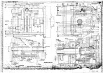
I can’t see any at the aft end as of yet – looking into the back of the main head gearbox with the side plate of the tail bracket removed. Incidentally do you recall if the set of keys at the facing slide end are the only ones, or are there any subsequent sets in the mid & aft section? The drawing I have (attached) appears to show only one set at the facing slide end.

15012021scan.jpg

Positioning the spindle shaft so the keys are horizontal is something I’d thought about for the very reasons you mention - the concern that the keys may fall out & then having to dismantle the whole head to put them back in again. My thoughts are to try & insert something (wood or similar) in the spindle tube to hold them in place ‘just in case’, while the spindle shaft is out.

On this machine the slots you refer to in the tail bracket are on the top (3 in total) & is where access to the 5/8” square drive locking screw/s that holds the spindle to the thrust bearing. According to the manual the useable length of the spindle can be adjusted by the user depending on how much reach is required.
Yes it was released before trying to bar the spindle. With it released the thrust bearing & carrier assembly is free to move while operating the handwheel (as if winding the spindle in/out).
IMG_3230.jpg

I’m office bound today, so will hopefully tackle it tomorrow.
 
Hi Tyrone

Thanks for your reply & info, it’s very useful & most appreciated.

I had a feeling that the bearing adjustment (through the window) was to do with either the main spindle tube or the facing slide & have left it alone.

As far as I can see the opposing keys that are visible from the facing slide end (with the spindle retracted into the head) look to be in good condition (not bruised or galled), but I can only see about 10mm or so at the moment.
I can’t see any at the aft end as of yet – looking into the back of the main head gearbox with the side plate of the tail bracket removed. Incidentally do you recall if the set of keys at the facing slide end are the only ones, or are there any subsequent sets in the mid & aft section? The drawing I have (attached) appears to show only one set at the facing slide end.

View attachment 311794

Positioning the spindle shaft so the keys are horizontal is something I’d thought about for the very reasons you mention - the concern that the keys may fall out & then having to dismantle the whole head to put them back in again. My thoughts are to try & insert something (wood or similar) in the spindle tube to hold them in place ‘just in case’, while the spindle shaft is out.

On this machine the slots you refer to in the tail bracket are on the top (3 in total) & is where access to the 5/8” square drive locking screw/s that holds the spindle to the thrust bearing. According to the manual the useable length of the spindle can be adjusted by the user depending on how much reach is required.
Yes it was released before trying to bar the spindle. With it released the thrust bearing & carrier assembly is free to move while operating the handwheel (as if winding the spindle in/out).
View attachment 311795

I’m office bound today, so will hopefully tackle it tomorrow.

That drawing brings back some memories. I'd forgotten about the double " Timken's " just in front of the main facing slide spindle bearing. You can see what I meant by the double tapered plain bearing that the facing slide spindle runs in. The later all " Timken " Electrobores had that arrangement but I'd forgotten about the plain bearing machines.

Given that you can run the travelling spindle independently of the facing slide spindle logic would suggest that there is another set of driving keys in the higher speed gearing towards the rear of the spindle frame. There definitely was on the later more modern machines. I wouldn't worry too much about those possible keys as long as you keep the spindle horizontal at all times.

I have had every bit out of those spindle frames previously but it is at least 30 plus years ago that I last worked on that model of machine. That's a long while ago. They are now dinosaur's really. The older Electrobores like yours were great boring and facing machines but they were a bit limited when it came to milling. The later machines changed that emphasis and you had a slightly lesser boring and facing performance, especially in terms of finish, but a much improved milling performance.

I've worked on lots of other Hor bores both previously and subsequently. Sometimes the " Kearns" machines etc etc get mixed up with the " Richards " machines in my head. Obviously they had lots of similarities.

I can't tell from the photo but does your machine have the spindle frame balance weight inside the column or outside the column. The first Electrobores came with the weight outside the column, the next modification had the weight inside the column. A later modification gave the spindle frame a more modern, squared off, appearance but was basically the same machine.

The last development of the Electrobore was a super machine with plenty of revs on the spindle, " Timken " bearings on all the spindles, DC variable feeds, power clamping to the tool, power clamping to the ways, power rotating top table, pre- select on the spindle speeds, all off the pendant etc etc. They were the best all around machines anywhere at that time.

Regards Tyrone.
 
Hi Tyrone

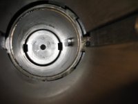
I’ve managed to partly withdraw the spindle from the tube which shows the cause of the issue – there’s a single key in the spindle tube in the aft section of the spindle frame (about 11” in from the end). There’s about 1/8 of it missing along its length that had quite a bur that was effectively preventing the spindle from moving freely.
IMG_3247.jpg

Once the spindle was withdrawn past this key it would slide easily in/out within the tube by hand. Rather than withdraw it completely I’ve left it at this point with the other end supported to take the weight.

I’m guessing because there’s only a single key, it provides the drive for the feed to the spindle/facing slide & possibly at some point in the machine’s life an operator has left both the facing slide & spindle feed engaged & locked it up (I’ve seen it done). They’ve probably managed to free it off & over time it’s worn to the point it’s at now.

I can reach it relatively easily & have tried to remove it from within the tube but it’s not moving. Can you recall if this key is retained with a grub screw as you mentioned a few days ago or if it’s a push fit?
 
Hi Tyrone

I’ve managed to partly withdraw the spindle from the tube which shows the cause of the issue – there’s a single key in the spindle tube in the aft section of the spindle frame (about 11” in from the end). There’s about 1/8 of it missing along its length that had quite a bur that was effectively preventing the spindle from moving freely.
View attachment 312000

Once the spindle was withdrawn past this key it would slide easily in/out within the tube by hand. Rather than withdraw it completely I’ve left it at this point with the other end supported to take the weight.

I’m guessing because there’s only a single key, it provides the drive for the feed to the spindle/facing slide & possibly at some point in the machine’s life an operator has left both the facing slide & spindle feed engaged & locked it up (I’ve seen it done). They’ve probably managed to free it off & over time it’s worn to the point it’s at now.

I can reach it relatively easily & have tried to remove it from within the tube but it’s not moving. Can you recall if this key is retained with a grub screw as you mentioned a few days ago or if it’s a push fit?

I " think " the keys are retained by two 1/4" grub screws drilled into the joint between the keyway and the key at either end of the key. They are drilled and tapped from the outside so you can't get at them easily. That's my memory of them but of course that could be what " Kearns " did as I've worked on both machines. You obviously wouldn't want that key to fall out in that position so how would you retain it ? The grub screws are the obvious way. Can you not weld a file onto a length of steam tube and reach in and clean up the key that way ?

Sorry I can't be clearer but old age is a bastard when it comes to your memory.

Regards Tyrone.
 
Hi Tyrone

Apologies, I’ve been meaning to post an update on this issue for a while but haven’t found the time.

The machine is now operational again, but it wasn’t going to make it easy for me.

Access to the key, although reachable was still a good 12” to 14” in from the rear of the main head gearbox/spindle frame & cleaned up quite easily with a file.
With the key now dressed I offered the spindle up for a trail fit, but it would only enter the bronze bearing (where the key is installed) by about ½” & then stiffen up again.
Measuring the bearing wasn’t that easy due to its location, so we made a plug gauge to the same dimensions as the spindle & used this to measure/gauge the bore.

After measuring, the bore of the bronze bearing had closed up in the area around the key……..only by a thou or so, but enough to bring it down to the same size as the spindle.

As already mentioned, with access being tight the use of mechanised tooling was out of the question, so the only option was to fettle the bronze bearing by hand.
With a block of wood fashioned to the profile of the bore with some linisher belt attached to it the slow process of fettling, blueing the gauge, offering it up, fettling & so on began.
Eventually after many hours (& an aching arm :ill:) the plug gauge would slide nicely within the bronze bush.
The spindle was offered up & this time slid all the way through.

Although the machine hasn’t been used since, I’ve had the spindle running while occasionally hand winding the spindle it in/out for about 5hrs or so while I’ve doing other work close by & so far is still free.

Many thanks for your help with this Tyrone, very much appreciated :cheers:

Yeah, I'm sorry but should have known that. It's happened to me in the past but it's a long while ago now and I just forgot. It's amazing what a small raised area will do when everything is such a close fit. Well done for sorting it out. Look after that machine and it will last you a lifetime. They were great boring and facing machines.

Regards Tyrone.


Back
Top