What's new
What's new

Sidney Taper Attachment

99Panhard

Stainless
Joined
Feb 22, 2006
Location
Smithfield, Rhode Island
My Sidney lathe, a 14-inch cone head, had a taper attachment. When I bought it (at a printing auction about 40 years ago) I got part of the TA. I'm guessing the rest of it was there but I knew so little about them at the time that I didn't see it and left without it. Now I have a project that may call for a fairly long internal taper and would like to get it working. I'm looking for:

Another one...
or parts for this one...
or photos of what it looked like on the machine so I can try to make the missing parts. If it involves elaborate castings, that may be an issue. If I understood how it worked it's possible I could fit something else.

Tomorrow, when I'm in the shop, I'll take some pictures of what I do have and post them. As it is, I don't even know how it worked although it looks as if you have to remove the cross feed screw and attach the saddle to the TA...is that normal? I've only had one in the past and don't think I ever used it. Ironically enough, I also have a partial TA on my tie-bar Hendey but that one is apart and some way from being useful.
 
Hi Joe

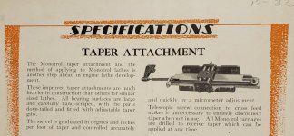
Here is a scan from December 1932 - stating by then you did not have to disconnect screw

20210520_092535.jpg

(Monotrol was a Sidney model)

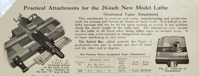
SB a few years prior made no such comment - so I assume you disconnected screw - even on this 24"

20210502_121320.jpg
 
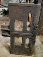
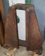
Thanks John. This is what I've got...

TA 2.jpg

TA 3.jpg

TA 1.jpg

I was able to puzzle out the dimensions for the bracket on the back of the saddle by working from that arm that clamps to the bed. While a casting is beyond me at this point, I am reasonably certain I cam make something that will work. What I can't figure out is how it connected to the saddle, or what went on the square portion of the swiveling piece. It is oriented with the square side up and the dovetail down - obvious from the graduation markings. Nothing I make will be as good as the original but I'm hoping I can come up with something workable...

What I have looks a lot more like the SB attachment than the 1930s Sidney. I'm guessing that the cast iron cover over the cross feed screw was supposed to be replaced with one having an extension reaching the TA. I don't have another cover buy if I think about it long enough I'll probably find a way.
 
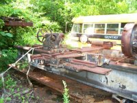
Here are some home made parts on this 24" Greaves Klusman I looked at in New Orleans in 2014. The bracket to the carriage saddle looks cast and may be original

P1000344sm.jpgP1000346sm.jpg
 
Thanks John. This is what I've got...

View attachment 321510

View attachment 321511

View attachment 321509

I was able to puzzle out the dimensions for the bracket on the back of the saddle by working from that arm that clamps to the bed. While a casting is beyond me at this point, I am reasonably certain I cam make something that will work.

I was missing the bed clamp for my Monarch CY. Provision of pix and a few basic dimensions from people on PM gave me enough info to fab one from steel as a welded assembly. It works fine. Not difficult.

As for the rest you need - NFI there I'm afraid.

PDW
 
99Panhard ,

In order to be able to use the cross feed in the usual way when turning tapers you need a telescopic taper attachment .

If your cross feed screw has a section that has splines or a long key way the length of the cross slide travel on it or tubular part with a female spline then yours would be made for that type of operation
Other wise you would need to disconnect the cross feed nut and feed in with the compound .
You can see two examples of the telescopic type in the links below one here on page 1 of the pdf for a Clausing,
http://vintagemachinery.org/pubs/182/25196.pdf

I have a Colchester similar to this one with the telescopic crossfeed screw assembly that is arranged a little differently and is shown on page 73 of this pdf from Vintage machinery
http://vintagemachinery.org/pubs/5286/9485.pdf

These might give some ideas for your machine otherwise you would need to follow something like the South Bend unit that John Oder posted with out the telescopic cross feed screw .
There may be some more about those on Vintage Machinery also.
I didn't check.
Vintage Machinery search links .
Clausing Industrial, Inc. - Publication Reprints | VintageMachinery.org
Colchester Lathe Co., Ltd. - Publication Reprints | VintageMachinery.org
Jim
 
I'm pretty certain that the idea was to remove the cross feed screw and use the compound to move the tool in or out. This is clearly a project that will take some planning. I've never actually used one. The TA on my Pratt & Whitney - many years ago - was complete but I've no recollection of even trying to use it. It was also quite different from this one so all these comparisons are very much appreciated. I'll have to go with something I can make, which can't be as elaborate as anything the original maker could do.
 
I'll see if I can get some photos of the bare bracket that bolts to rear of the carriage saddle for the 20" Heavy GK. You can see some of it here with related parts

100_1963.jpg

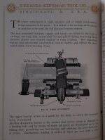
Here is a GK T/A page from about early twenties

20210522_084205.jpg
 
Thanks John. That appears to be very similar to the Sidney which is also, I believe, from the early 20s. I've worked up a plan for the bracket - which must have been a casting. My question about the dovetail angle concerns the dovetail on the bottom of the 2-part piece that adjusts the angle. I don't want to make any modifications that would preclude using original parts should they ever show up so I have to make the bracket to accept the dovetail that is there. I'm reasonably sure I can do that although not as precisely as the factory could.

Another question...I have never seen one of these work so I am guessing that the dovetail is there to adjust the location of the TA and that the swiveling piece is locked in place when working and the taper is controlled by the slide on the top of that piece...is that correct? If it moves in the dovetail it makes getting the angle perfect a major consideration. If it doesn't, things are much easier although I suspect my design will be more complicated to use than the original was.
 
I have never seen one of these work
Bottom (non swiveling) piece stays still (see the bed way clamp and its rod?) while the carriage moves the T/A (such as the bracket talked about in an above post) in relation to this lower slide,

The upper piece is adjustable for taper or angle and is clamped solidly to the lower. It of course is also stationary in relation to moving carriage

Cross slide has to move "in or out" as the carriage moves - because it is attached to the piece that slides along the dove tail on the upper angled slide as the carriage moves
 
Here are some GK pieces:

Lower bracket. The small "tab" mounts the upper bracket

20210522_134416.jpg20210522_134608_002.jpg

Lower slide - for whatever reason, GK thought this should be 50" long. The "ears" support the upper slide when it is considerably angled. We are looking at the bottom

20210522_151549.jpg

Upper bracket - a feature of later designs. "Boxes" the works back there

20210522_135917.jpg


Back
Top