What's new
What's new

United States Air Compressor Co of Cleveland 2-stage

magneticanomaly

Titanium
Joined
Mar 22, 2007
Location
On Elk Mountain, West Virginia, USA
I'm tired of having to start my old tractor with the little air pump driven off the belt pulley, every time I need to fix tires. So today I dragged a project out from under the piece of tin that has sheltered it for maybe 20 years, ever since I rescued it from the scrapyard, and into the toolshed.

When I acquired it, it turned freely for most of a revolution and stopped with a clank. Now it is stuck, and clanks when I roll it over.

It is interesting. Intake is through the hole visible in the top of the crankcase, , presumbly to muffle noise, and discharge is similarly muffled through the base. WAG first stage bore around 3 1/2", second 1 7/8"

Will report as I tear it down.Ccase cover side 9 1 18.jpg
 
MagneticAnomaly wrote:

"So today I dragged a project out from under the piece of tin that has sheltered it for maybe 20 years, ever since I rescued it from the scrapyard, and into the toolshed."

It came from scrap and to scrap it shall return; it's just a matter of time!

The only question is whether or not it still has any useful life to it!

If it proves to be impractical to repair, you will at least have fun trying to repair it. (This should be at least as much fun as a hit-and-miss engine.)

From the context, there was no extra cost to you from storing it, and no shortage of space resulted from its outdoor presence.

This old thread may be relevant, or not:
http://www.practicalmachinist.com/vb/general/united-states-air-compressor-co-225363/

Keep us posted!

John Ruth
 
That should restore ok,just needs patience in freeing it all up. Neat little compressor. My little Broom-Wade was in a similar state on a farm scrap heap-it don't half blow up tyres quickly!
 
" it turned freely for most of a revolution and stopped with a clank." Wow..this sounds serious. A wire brushing and a can of Krylon might not bring the much touted 'happy ending'. Good luck and take pictures.

Stuart
 
Ya the clanking and stopping is not a good sign. But OP will find out for sure when he tears into this. I bought a parts pump for my 1940 4cyl Champion. It turns relatively quietly and then comes to screaching clunking halt. I do not need any parts right now so I am not going into it. But it is not a good sign at all. A few years ago at industrial auction I picked up a Gardener Denver ACM on 80 gal tank for a couple of dollars. Bought it for the tank, but took the compressor apart that was froze solid. What a mess. The only hard parts I found that were worth saving was the head. All other moving parts were scored or broke. Like it may have run out of oil before self destructing. Junked the pump out saving only the head. After a few years I finally tossed it out. Within a month got a call from RR museum looking for valves for a GD ACM pump that was on our 45 Ton GE switcher. Eventually we found new valves and springs. These old compressors are are very cool but good luck finding parts. You have to develop some good detective skills. Hard parts if you can find them from a supplier are usually more than the pump is worth. But old recips are cool things to restore and keep running when you have the interest. Had a nice older Leroi 800 pump that got sold off because of a few parts costing more than the whole compressor was worth. Lost money on that adventure. OP please remember to post pics of what you find on this compressor. Regards, John.
 
I hope nobody was holding his breath, waiting for the rest of the story on my USAC compressor.

It's apart. First took off the pipes. 5/8 copper tubing from the uppercorner of the crankcase to the LP inlet, ¾ copper from LP outlet toHP inlet, 1/2” copper from HP outlet to a manifold cast in thebase. Inverted-flare fittings.


Four3/8-24 studs securing each head cameout without trouble (except that it was the studs that came outinstead of the nuts coming off) The HP side valve plugs were toughto get out, but the only thing that got broken was an easy-to-replacebrass 3/8 pipe x 1/2” inverted flare street elbow. Four identicalbrass disc valves. The LP ones needed lapping.


Heads off dislosed some rusty sludge in LP cylinder, rust streaks in HP..donot know if there is serious actual pitting yet.


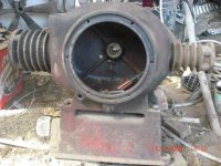
Crankcasecover/bearing plate off revealed why I found it at the scrapyard.


The LP piston isdriven by an ordinary-looking connecting rod from an ordinary lookingsingle-throw forged steel crank, with two oil-splashers attached to itwith roundhead screws.


Piston is long,2x D or more. Skirt is round, not cut away, with a heavy internalrib around it, and the pin bosses extend all the way to the bottom ofthe skirt, They are tapped 3/8-16, for two hex head capscrews thatsecure to it a...”yoke” I guess you could call it.


The “yoke”is a hollow casting, through which the con-rod passes, and that alsothat goes around the big-end and crank-throw, all the way to theother side of the crankcase, where it has a 7/8” hole coaxial withthe LP piston seat. Through that 7/8 hole passes the turned-down and7/8-14 threaded end of the HP piston, which is secured with ajam-nut.


This descriptionis incomplete, because it failed to mention that the yoke lay in manypieces in the bottom of the crankcase. The threaded end of the HPpiston was still in a piece of the yoke, but had broken off thepiston, which itself lay in the bottom of the crankase. With a bigmouse-nest and the mummified remains of its owner.


Not sure if Iwill weld the yoke back together, or fabricate a new, steel one. Either way I will have to figure out how to get the two oppositepiston-mounting features precisely coaxial. Need to make one plainand one Napier-style piston-ring for the HP piston.

Oddly, the 7/8-14 nut, and both con-rod bolts were loose. Did someone have it apart and fail to tighten things, and was that the cause of the failure?


Bearings look CIMG1863.jpgCIMG1862.jpgCIMG1861.jpgCIMG1860.jpgCIMG1859.jpglike babbitt, and along with the journals look in perfect shape.
 
More pictures.

First picture in last post is of the oil-level sight-glass. It has a little stand-pipe, to vent it I guess although the cap that secures the glass tube also is vented. Should there not be some sort of loose cap over the standpipe to keep dirt out?
 

Attachments

  • CIMG1858.jpg
    CIMG1858.jpg
    95 KB · Views: 55
  • CIMG1857.jpg
    CIMG1857.jpg
    95.9 KB · Views: 52
Magneticanomaly:

It is always interesting to follow your adventures with old iron. I've seen a few of the opposed-cylinder compressors over the years, and they were always quite old. Riding 'Airhead' BMW motorcycles for over 45 years, I am obviously quite partial to the 'boxer' design of engine (and compressors). Your explanation and pictures of the internals of your compressor are quite interesting. Namely, one connecting rod working both 1st & 2nd stage pistons. The obvious reason is that the U.S. Compressor Company wanted to keep the crankcase and overall width of the compressor as compact as possible. On my 'Airhead' BMW engines, there is an offset between the centerlines of the LH and RH cylinders, and the crankshaft has two separate throw journals. Makes for what is referred to as a "Boxer" engine, with the forces setup by the pistons and rods cancelling each other. I joke (never tried it) that I could take a Pilsner beer glass and fill it to the top with water, and it could stand on the motorcycle's gasoline tank with the engine running and not slop a drop of water over the rim of the glass. Your compressor, on the other hand, is somewhat reminiscent of the British twin cylinder motorcycles which had both pistons on the same crank throw, so built some heavy vibration from the 'unbalanced reciprocating mass' (so much for counterweighted crankshafts). I wonder if U.S. Compressor figured they'd save money by this design, doing away with a wider crankcase with offset cylinders, and doing away with one connecting rod and getting a narrower crankshaft in the bargain. The casting and machining of the yoke and the method of connecting it to the piston seems like more machine work and probably was a wash in terms of cost vs a more conventional design. As slow as the old compressor turns, and with all the iron in it, I am sure the forces setup by the unbalanced reciprocating mass (along with an un-counterweighted crankshaft) are not an issue.

For what forces the yoke sees in service, and as badly broken as the yoke casting is, my own 'druthers would be to make a new one out of steel.

As if I can't get enough of boxer engines on my motorcycles, one of my old Lincoln welders has an Onan 'boxer' engine as well. Smooth running machine in both how the engine runs as well as how it lays down weld.

I believe a company called "Champion" also built an air compressor with the opposed-cylinder design, probably in the 'teens or 'twenties. It was evidently a design that fell out of favor with compressor builders, probably due to manufacturing costs.

My own shop air compressor is a Worthington. It dates to probably the 1940's or early 50's. It is a two-stage vee configuration, direct driven at 1750 rpm via 'Thermoid' ("rag joint") type coupling. It is quite a well built little compressor, having an intercooler made of copper with finned tubes, having a soldered-on tag from 'Harrison Radiator'. The intake air filter/dampener is a vintage 'Air Maze' unit, as was seen on old cars. There is a cast iron dampener chamber hung off the 2nd stage discharge, and the flywheel is configured to take the rubber/canvas coupling disc as well as having closely spaced fan vanes. The compressor sits on a 120 gallon ASME code tank that came off an Ingersoll-Rand T-30 (? as to model) that bit the dust after a short operating life. The older compressors were quite well built, and with any kind of maintenance, seem to last a long time.

On our tourist railroad, we had a Porter center cab diesel locomotive. This locomotive was built in 1940 and spent its working life in the Portsmouth, NH Naval Shipyard. It had two Cummins diesel engines(which the Navy had replaced just prior to surplussing the locomotive) , Westinghouse generators/traction motors, and each engine had a Gardner-Denver compressor for the airbrakes. After a few operating seasons one of the Gardner-Denver compressors was in a sorry state. I could not find Gardner-Denver parts. These were original 1940 two cylinder compressors. I had the railroad buy two new Quincy compressors (I forget the model number). These have the automotive style pressurized lubrication system and spin-on oil filters. Those compressors and the Cummins engines outlasted the rest of the locomotive. Each truck has the traction motor sitting perpendicular to the axles, and drives via a bevel pinion on the motor shaft and "crown gear" for primary reduction (and turning the drive parallel to the axles). A final reduction is made with a pinion and bull gear on one axle of each truck. Power is transmitted to the other axle of each truck by side-rods. Some years back, one of the drive pinions came loose on a traction motor shaft and bent the ring gear and did a bunch of damage in the gear case. If my Worthington compressor ever gives out, I will make a bid for one of the Quincy compressors on that locomotive.

Interestingly, when I ordered the Quincy compressors for that locomotive, Quincy was changing the design of their cylinder and head castings. One compressor has the 'old' pattern with more/finer cooling fins, while the other (same model) has the 'new' pattern with fewer and 'clunkier looking' cooling fins. The old opposed cylinder compressor and the crankcase end casting are nice pieces of the patternmaker's art, as was the yoke. Quincy obviously was looking to save a few bucks on each compressor when they 'modernized' the cylinder design. The older machinery definitely had some 'eye appeal' in the design of cast parts.
 
Yes, I like air compressors. Have a collection, all probably in condition comparable to the USAC. It was petty random, which one I pulled out to work on. I guess I think this one will need less hp than most of the others, so will be usable more often on the solar-power system.

My guesses about why the opposed design is not common today:
1. alignment of cylinders difficult if they are separate castings, and you need a looong stepped boring-bar and tandem hones, if a single casting like this one.

2. takes up more space than if side-by-side.

I am wondering about the vibration issue, too. I guess five pounds of reciprocating mass. Perhaps design speed is very slow. Pulley must be 20" diam.

There is at least one good reason for the setup. Discharge stroke of LP cylinder coincides with intake stroke of HP.

I have one more idle question, and one practical.

The idle question has to do with efficiency lost by poor internal "aerodynamics". The compression spaces are connected to the transverse valve chambers by a 1/2" drilled hole coaxial with the bore, with sharp edges. Must be a lot of heat and turbulence there. I guess the "T-head" or transverse valve orientation was chosen so as not to make the whole machine even loooonger, and the small hole was an effort to reduce dead volume. Another reason to go with vertical cylinders, side-by-side, so valves can be on top of the pistons.

The practical question has to do with the air intake. I am not sure if the photos show it, but the air intake pipe to the LP stage connects to the back wall, near upper back corner, of crankcase. Surely the air in the crankcase is full of oil mist. Air is supplied to the crankcase by a 1 1/2" hole in the top of the front corner directly opposite the pipe connection. Free ingress for dirt, and mice.

Even if the unit originally had an air-cleaner stuck in the hole, I see no sign of any internal tube nor effective baffles to keep oil mist out of the intake air. Great for the cylinder lubrication, until it decides to Diesel. Soot was most of what made the HP discharge valve so hard to remove.
 
I have a similar, if not the same USACO compressor pump. Mine does not have the little vent shown in image #1, post #7. Mine isn't in use, but runs and has yet to see any disassembly or TLC.
 
Reggie,

The vent you refer to is a sight-glass for oil level.

Is your compressor all-together, with a motor and tank? If so, what hp and speed is the motor? What size pulley on it?

Is that air intake hole at corner of crankcase open on yours, or is there some kind of air-cleaner attached to it?
 
My compressor is assembled and was working until I removed what was an electromagnetic check valve to determine why it failed. It has a Wagner motor, which I believe to be original, 3/4hp, 1725rpm, 2-1/2 motor pulley which isn't original as it's now V belt driven. Compressor and tensioner still have flat belt sheaves. Crancase does have a breather cap.

IMG_20220324_130503688.jpg

IMG_20220324_130442129.jpg
 
Thanks for posting the picture of yours, Reggie. I am guessing it is older than mine, mostly because (if i understand you) the pully has no groove for vee-belt.

The other obvious major differences i see are that the bearing plate on side facing camera is rectangular (mine is round); and the valves on your HP head are side-by-side instead of in a tee arrangement as on mine.

I would love to know if the internals are the same. Somebody suggested in the other USAC thread that there would be a Scotch yoke, but not in mine. I will take and post a picture tomorrow of the yoke that connects the H and LP pistons in mine. I barely stuck all the pieces of it together tonight with crazy-glue, so I could see what it needs to look like, and take some measurements for the steel replacement I will make.

Your LP intake pipe goes around the back....does it connect to (suck from) the crank-case?
 
Mine was flat belt driven, both the pump and the tensioner have their original pulleys.
LP intake pipe does connect to the to of the crankcase in the rear.
Is your pump an H3A or some other model?
 
I have not seen a model # on my pump, just a S/N I will try to attach a picture of the shattered yoke, which I crazy-glued back together to help me measure it and plan how I will build a replacement. I should have included a scale in the picture..it is about 7 5/8" OAL

It weighs about 4 1/2 lb, HP piston weighs 2, LP piston and con-rod another 4 1/2....over 11lb uncompensated reciprocating weight!

My pulley is about 18"PD, so if I use a driver the same 2 1/2" diam as Reggie's and a 1725RPM motor, it will go about 240RPM.

Wish I knew what busted the yoke.
 

Attachments

  • CIMG1874.jpg
    CIMG1874.jpg
    93.2 KB · Views: 18
  • CIMG1873.jpg
    CIMG1873.jpg
    92.5 KB · Views: 16
Magneticanomaly:

I used to get asked to play detective when things at the powerplant went bust. "reading fractures" and looking for tiny clues was what it was about. Doing the forensic analysis as to why an aftermarket rear wheel failed on a Harley-Davidson as part of a case my brother was handling as attorney resulted in his paying my fee with a new Harley Lowrider. Playing detective with damaged (or worse) machine parts is kind of an offshoot of my engineering.

One thing I took to doing when looking into why something failed is to put my mind into the era that the failed machinery or structure was designed and built. In the 1920's, things like 'aviation' locking or safety wiring was not yet developed, nor were such things as nylon-insert locking nuts or 'Loctite'. For things like con rod big end bolts, the nuts were often 'castellated' and secured against loosening with cotter pins or soft-steel tie wire. Or, soft sheet steel 'bend up tab' locks were used.

My guess as to what busted the yoke is likely fasteners working loose. The 1st stage piston was held to the yoke with two capscrews, and the 2nd stage piston rod was held on with a nut. If either of those fasteners worked loose, the result would be a pounding and eventually an interference/crash. Looking at the damage, my first thought is the big end bolts on the connecting rod worked loose. Rod flailed around and broke the yoke casting. If fasteners tying the LP piston and HP piston rod to the yoke worked loose, there would have been damage in those areas. The way the yoke casting is broken, it looks more like the big end of the con rod came loose.

When US Compressor first assembled the compressor, whether they could have used soft steel 'mechanics' or "tie wire", cotter pins, or used a 'bend-up tab' to lock the nuts on the connecting rod big end bolts. Any nicks from bending up the tabs or cotter pins with drift punches, cold chisels or similar could eventually cause an in-service failure due to continued stress cycling. Or, they may simply have used 'cut' type lock washers on the big end bolts. I've seen quite a few cut type lockwashers that failed in service. When we'd go to take things apart, we'd put the torque to the fasteners, and when we got things loose, there'd be a lock washer in two pieces.
This was on 'static' type connections or joints. On something like a connecting rod big end, with the kind of stress cycling, it is entirely possible a cut lock washer on a big end bolt failed in service. Once that happened, the big end worked loose, and the compressor likely ran for some. Being a slow speed/loose tolerance machine, the compressor could clank and pound along with a loose con rod big end for some time. Eventually, the loose big end bolts may have either had the nuts work right off them, or from the looseness, were subject to a bending fatigue. Either way, once the big end bolts let go, the crank throw probably drove the big end into the yoke casting and busted it to bits.

A garage air compressor is often one of those things that just sits in its spot and 'perks along' for years without any sort of maintenance or attention. An old slow-speed compressor like yours would be the kind of compressor that fit this sort of description. No one bothers to blow down the air tank to drain condensate, and no one bothers to check, let alone change, crankcase oil. Unless the drive belt slipped or the motor failed to run, this was the kind of compressor that was 'let go' for years in some automotive repair garages or similar shops. Your compressor probably ran for ages, started to clang and bang, but no one paid mind of it until things went bust and locked her up. At that point, maybe someone got into the compressor, determined things were 'FUBAR' and put it aside as one of those things they meant to order parts for and never did.

Back in the days when I met you and we worked on that East River kinetic turbine (or whatever high-falootin' name it had), I was quite impressed with your knowledge of machine design and engineering. As we both frequent this 'board and seem to have an affinity for old iron, I am sure you have also got a sense of how conservative design practices were years ago for machinery and the like. On your compressor, chances are the bearing loads on the crankshaft throw and main journals were figured at some ridiculously low (by today's practices) values. As such, if a big end worked loose, with the low rpm/low piston speeds, the compressor could clank along for some time. If the compressor was off in some odd corner or another part of a shop, the anvil chorus in the crankcase went unheard and unheeded. Older slow speed compressors always remind me of a percolator type coffee pot on my grandmother's gas range. The old compressors tend to make a noise similar to a beat up aluminum percolator, and it's one of those sounds you hear in older automotive garages and shops and take for granted. Some people, to save floor space in a shop, would put a compressor up in a loft, out in another shed or lean-to, or similarly get it out of the working space. Seen it a number of times. In those locations, with a compressor 'out of sight', it is also 'out of mind' until it self destructs as yours did. Seems like the yoke might be nice exercise in forming some A-36 steel to approximate the shape of the casting and then welding the steel parts together. I'm sure a fabricated steel yoke will be a major improvement over the original casting, given the kind of loading that yoke sees in service. I toyed with the idea of a casting defect that eventually propigated into a crack, but without seeing the fractures on the casting, let alone the fact that time, dirt and much else would 'muddy the trail', my mind keeps pinging on the loosening of big end bolts as the more likely cause of the failure. I've been wrong many times with my theorizing, but it's always a fun exercise (and sometimes quite profitable).
 
JohnK, I have seen several old reefer compressors..have one here that used to run on SO2, that's another story. But i have never seen a reefer that was 2-stage, nor one with a big open hole into the crnakcase (he air intake), nor without ealborate mechanical shaft seal. This one has the first 2 and lacks the third.

Joe M., yes failure analysis is a blast. If all the fracture surfacs were not rusty, we could probably tracer propagation, or at leastg see if it was an all-at-once or progressive failure.

Some details I did not mention:

Con-rod bolts have castle-nuts and split cotter-pins, and were loose, but cotters were intact when I opened the case.. Capscrews that held the yoke to the base of the LP piston were snug but not tight. The inboard end of the solid cast-iron HP piston was turned down and threaded 7/8-14, and held in its end of the yoke with a jam nut and slit lockwasher. This once-integral stud was broken off the base of the piston, and still in the end of the yoke, but that nut was also only finger-tight.

It almost looks as if somebody had it apart and did not tighten anything, put it together and ran it until slight looseness developed into hammering.

My other guess is that the cast-iron stud on the HP piston broke off.....Overtorque" casting imperfection? slight misaignment leading to fatigue in bending? The second two I could see if the surfaces were not first hammered and then rusted...but I will clean them better and look again.

If that was the first "event", the HP piston would have gone through its compression stroke fine..then stopped until the LP delivered enough air to it to fire it into the crankcase like a bullet. The impact migth have broken the yoke, or one or both pistons might have had insufficient suport in their bores to avoid light cocking, which would have caused collision onthe next stroke.

When I found it, the ENTIRE HP piston was inside the crankcase, so the LP kept pumping even after the yoke shattered. Intact yoke would have prevented the HP piston from coming that far in.

I doubt the torque form the motor alone could have done so much damage. FW energy and that 14,000 grain air-gun bullet must have done the work, in only a couple of revs before it jammed up


Back
Top