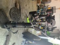
Time for an update. The whole machine was covered in gunk and what I assume was 1/4” thick of bondo. I decided to wire wheel it all to bare metal and then I coated it with penetrol to give it a nice shiny appearance while remaining dry and protecting from rust. This has taken an immense amount of time, but I am just about all done with the cleaning. After this I need to do some machining, which I will probably make a more in depth post later about for advice. After that I plan on pouring new Babbitt bearings, which will be a first time for me. But for now I am focusing on finding/making the missing parts and cleaning up the last few pieces.
Thanks for the great info jhruska. Fortunately clodbuster was able to give me the specs of my missing gears. Unfortunately they are not off the shelf gears and I will have to have them custom made. I am not a machinist, but I hope to start learning and have my own shop one day. For now, I need some advice!
First question, once I measure the diameter of the bores for my missing shaft, what kind of clearances do I need? The shaft does not rotate, and has a set screw to retain the shaft, so I don’t think it needs a super tight press in fit. I need to get some calipers, but say the bore is .500 how much smaller should I make my shaft? Also, how much larger than the shaft diameter should I make the bores of the gears that spin on the stationary shaft?
To go with that, how should two separate gears directly next to each other with no hubs on a stationary shaft be connected?
For the quill, right below the top retainer (not sure what this is called) that threads against the quill, is some sort of red rubber or plastic bushing or seal or something. What is this? Mine is cracked in half and I would like to replace it.
Last question, I need to get the worm off to clean up the cast part and to replace the bolt that’s trapped by it. Any ideas on how to get the pin out? I tried punching it out and broke a few punches, it just doesn’t want to come out. I’m scared of drilling it because The pin is at a weird angle.
Sorry for the flipped image, no matter which way I flip it the forum flips it the wrong way, not sure how to fix it. Thanks for any help!