What's new
What's new

What is the maximum spindle speed on older cone drive spindles?

Dr. Hillbilly

Aluminum
Joined
Dec 6, 2019
Location
Oregonia, Ohio
When my LeBlond and Hendey-Norton were converted to electricity long ago the motor speed and pulleys selected provided an increase in spindle speeds of about 20%. If I crank my VFD beyond 60Hz I could run them at twice their intended speed.
Obviously there are no fatigue issues as there would be with rolling-element bearings. Generation of heat is the other obvious concern. If the bearing cap is cool is all OK? Who has experience with increased speed of spindles?
 
What are the diameters of your lathes? Are these plain bronze bearings with drip/wick oil cups? Are you wanting to run carbide cutters or will you be sticking with HSS?
 
Fastest Hendey speed was on the smallest of course. Steel on "white metal" or Babbitt have limits directly related to load - a reason lathes go slower than grinding machines - they are expected to have much rougher lives

https://www.practicalmachinist.com/...-head-spindle-speeds-191988/?highlight=speeds

There were HIGH SPEED Hendeys - but they were with equipped precision class angular contact ball bearings - you can tell by the HUGE bearing housings on a very small lathe

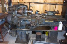
shop pics 07_0124.jpg
 
Steel on "white metal" or Babbitt have limits directly related to load - a reason lathes go slower than grinding machines - they are expected to have much rougher lives


View attachment 279431
I appreciate the multiplicative impact of appling high loads at high speeds. I would consider the experiment a success if I can cut at high speed at low loads, and low speed at high loads. It would be nice to be able to run faster with small diameter work, small diameter tools, or occasionally carbide tools for finishing.
 
CMM playing around in 1913 with huge HP , high cutting speeds and massive flood coolant - probably showed them how far they had to go yet to get the machines suitable for such day in, day out abuse

Mill Performance 1913.jpg
 
I appreciate the multiplicative impact of appling high loads at high speeds. I would consider the experiment a success if I can cut at high speed at low loads, and low speed at high loads. It would be nice to be able to run faster with small diameter work, small diameter tools, or occasionally carbide tools for finishing.

"Small diameter" also implies low-mass, so...

"So long as..." you have and maintain a nice, tight, low TIR OEM spindle - EG: do NOT abuse it..

... you ALSO have a nice, stable MOUNT.. for a smaller diameter SUB spindle with bearings of its own.. that can be put into place much as a collet and drawtube, and powered at the arse-end with a motor of its own.

If it means that much, you could even seek a lathe with a wider native RPM band.

"See also " Globe Milling Attachment, Tony's archives website. Solves SEVERAL challenges, that one does:

Globe Milling and Dividing Attachments

The concept is not limited to the OEM 1:1 drive ratio, is it?

Love to see a more energetic PM'er replicate at least HALF the functionality of that neat bit of kit.

Even so... for many among us "nice to be able..." comes up several times a week, but isn't a strong enough motivator for powering anything harder to manage than a "nice to.." off our keyboard, though.

:)
 
I have always liked the globe setup. Even owning large and small milling machines, I still want one. The likelyhood of ever even seeing one in person is zilch.

Personally I would keep the top end rpm within 50-75 rpm of the original. With today's lubricants you can probably push your luck a little bit. Best bet is to stick with what was recommended.
 
One has to consider that an important limiting factor of "overclocking" an old lathe is the geartrain at the left of the spindle not having adequate lubrication for much faster speeds.

Paolo
 
I have always liked the globe setup. Even owning large and small milling machines, I still want one. The likelyhood of ever even seeing one in person is zilch.
Ditto on the mills - that's not what I'd want it for at all.

The ability to extend swing is "neat', but that isn't something I need, either. My larger mill can easily beat that.

The "attraction" is in something it could do, but I haven't actually seen done. Not yet.

It is set up with 1:1 pulley ratio to the spindle. That could as easily be a 3:1 step UP. Maybe 4:1? Maybe more, yet?

No pressing need, here. 10EE's and HBX-360 are fast enough as-had.
 
"

"See also " Globe Milling Attachment, Tony's archives website. Solves SEVERAL challenges, that one does:


:)

I had seen the Lincoln Miller, but not the Globe, which takes the concept much further.

I did something a bit like this years ago on a 3-axis machining center:
Mounted the lathe tools to the table, in a line, like on a swiss machine
Chucked the short bar work in # 40 collet holders in the tool magazine
Used the machining center tool changer as a robot loader
Used the milling spindle as a lathe
The ATC was faster than a robot load
And the rapid time from one lathe tool to the next was faster than any turret index
But limited to light turning of short work (no tailstock, sub-spindle, and no interrupted cuts)

IF... I had the need.. or maybe someday just for the Halibut..

it would make more sense to acquire / restore a tiny "instrument" class lathe.

Bigger than "watchmaker", but still small enough to - for example, swing the massive rectangular table of the Alzmetall DP to 90 degrees, adjust height to a comfortable level, and then..

Pull the "planked" mini-lathe out of the storage drawer, drop it into the massive vise, do the do, clean it up, and put it back in the storage cabinet.

Near-zero need of "extra" space. Very little labour to "ingineer" a plate, drive, (PM Dee Cee, probably) and mount.

Power, RPM, hand control sizes, workholding and tooling all appropriate - and no monster rotating-mass drivetrain or workholding inertia to finesse.

Next size up from a Derbyshire?

The AB5/S table's top is around 2 feet front to back, just under 3 feet wide, fairly well "attached" to around 4,400 lbs Avoir as part of the whole drillpress, even has coolant recovery trough & plumbing with chip filter.
 
CMM playing around in 1913 with huge HP , high cutting speeds and massive flood coolant - probably showed them how far they had to go yet to get the machines suitable for such day in, day out abuse

View attachment 279449

I am addicted to paradigm shifts, and love it when the envelope is pushed.
I had missed this great example from CMM.

It is not yet vintage (1980's), but I enjoyed the example below. I played a minor role, working with Alex Slocum on some of this, particularly the turbo tool on page 50.
100kW (130 hp) at 100,000 RPM is exciting!
http://blog.ncut.edu.tw/userfile/3120/17_CasesStudyforHydroststicBearing.pdf
It is speculated that the power system would cost around $100k, but that is not what the initial system cost. An old fire truck (a big pumper, nearly 500 hp) was parked behind the machine and supplied water for the bearings and drive turbine.
This offered a "modern" alternative to the lineshaft. Rather than a shaft overhead shared by all machines, a water pipe would supply all machines with coolant at 1000 psi and high volume to drive hydraulic turbines, replacing the electric spindle drives...
 
Dental surgery and perhaps a counter rotation to cancel out the stress in the head. Two at once. I like the idea of lubricant with pressure flooding the bearings. Two filters and circles back. It is supposed to be the film, not riding ... the once accurate bearings. We cannot disregard the weight of these shafts with gears and heavy pulleys. They aren't bearings we are comfortable with. They need driven from above or otherwise than below. The shear weight, wears out the lower bearing and then the spindle isn't concentric under load. Then good ( maybe "vintage") machines go to scrap because they cut wrong.
 
The Hendey Norton is. Suspended in time with an overhead motor ( which is a marvel itself) and they knew.
 
Put seals on both sides, drill a drain hole at the bottom, pump in oil. Then you can spin it as fast as you want.


A client tried that with ball bearings at 60k rpm. Took maybe a minute to burn them up to where the balls were little squarish bits.

I was there when they did it, but that was not my part of the project. Dunno what they eventually did, but I saw it work OK later.


Back
Top