What's new
What's new

Yost Vice parts

epoclaen

Plastic
Joined
Apr 12, 2012
Location
Pennsylvania, USA
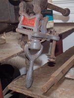
I have an old Yost #30 vice with 5" teeth and a roughly 8 or 10 inch grip range. I'm lost on the parts I need for the base though. I assume it's a turnable vice but those usually have locking bars on the top face which this has no holes for these. So is this truly a turn-able vice or is it a static vice? If static, why the teeth in the base and the two in the vice base? Is it possible that the base isn't for this vice? What is needed to attach the base to the vice (and where do I get one)? Is the large pintel with cotter pin hole shown a part of the vice? What grade of bolts should I use to secure it to the bench?

Thanks!
Jeff
GEDC0110.jpgGEDC0111.jpgGEDC0112.jpg
 
The large pin with the cotter pin hole is not part of the vise.

If the vise mates up and seats into the base casting, then it is for the vise you have. If the vise were a fixed base vise, it would have mounting ears cast integrally with the body of the vise. Since the vise body has no ears on it, what you have is a swivel base vise. It was capable of turning 360 degrees in relation to the base (the part with the raised teeth and mounting "ears"). The vise looks like an earlier design. IMO, from your photos, the vise relied on a center screw to lock it in position on the base. That would explain the lack of clamping screw holes in the base flange on the vise body (the horizontal surface below where the casting has the raised lettering).

Another guess on my part is what you have may well have been a combination vise. It appears to have recessed pockets in the jaws with setscrew holes. These were to take pipe jaws and enable the vise to be used for multiple purposes. The base flange of the vise body does not have any holes for the usual clamping screws (to lock the swivel base), and seeing the two teeth on the underside of the base of the vise body leads me to think this was one of the "portable" vises sold years ago. These vises had a center clamping screw with a swivel handle/nut. The idea was that the vise could be taken to a jobsite and mounted by drilling one hole in anything handy- a part of the building framing, a saw horse, truck or wagon bed, or temporary workbench. The two shallow "lugs" or teeth on the underside of the vise body would then bite into the wood surface the vise was being clamped to and keep it from moving around. Trades like plumbers, electricians, ironworkers, or millwrights or boilermakers might have used a vise like this on jobsites.

The hole thru the base casting and the tapped boss in the center of the bottom of the vise look like they were meant to take a clamping bolt.
My guess is that the vise had a long clamping bolt. It was heavy, and had a shoulder on it to seat against the underside of the mounting casting. It had male threads to screw into the center tapping in the boss on the underside of the vise. Chances are this clamping bolt was made long enough to extend dowbn thru a bench top. The mounting casting was located on a corner of the bench top, and a clearance hole was drilled thru the bench top in line with the hole in the center of the base casting. This center bolt may have had a handle on it (a sliding tee bar similar to the vise screw handle, or a swivel handle). This center bolt pulled the vise down solidly so the teeth on the vise engaged and seated into the teeth in the base casting.

To secure it to the bench: what kind of bench top are you planning on ? Wood or steel ? Grade 5 or Grade 8 bolts are plenty strong enough. If a wood top, make sure to use some sort of large heavy washers on the nuts to keep them from pulling up into the wood top.

The center bolt & swivel nut should not be a hard part to "reverse engineer" and make if you have a lathe and some hand tools. Yost still exists as a vise manufacturer, but I think they may have merged with some other firms and relocated. One of the last US Made vises.
 
Maybe the under-the-bench clamp was a camming device as has been suggested, but the ones I've seen were essentially nuts. Somebody with skills searching for patents could probably find Yost as the assignee of a patent for this base and clear up the question.

The under-the-bench clamping nut that Joe describes can take several forms.

One type has a sort of attached wrench. Joe's description as a "swivel handle/nut" is about right. First, think of a "breaker bar" from a socket wrench set. Then, think of a nut with traverse holes on two sides and a handle with an end like a shackle pinned into the hole. You take a half turn and then flip the handle for the next half-turn. The nut does not need to be hexagonal.

Another sort of clamping nut for these vises is a giant wing nut with curled-up pointy wings, best made by your friendly neighborhood blacksmith. (Yeah, that guy under the spreading chestnut tree!) The more graceful the pointy wings, the better. I've seen them looking like long-horn cattle and others like a Cape Buffalo. (Clean-out hand-holes on old steam boilers had something similar, but you aren't likely to find any of those laying about.)

As I'm writing this, it just occurred to me that if one took a heavy-duty marine rope cleat and drilled & tapped a hole up the center, it might make an ersatz under-the-bench wingnut.

Maybe someone has one of these vises and can post photos of the clamping arrangements.

JRR
 
John Ruth's post gave me a flash: Reid Supply offers what they call Malleable Ball Handles, on page 64 of their 2012/2013 catalog. This is a handle which consists of a round hub with two lever handles at 180 degrees to each other. I do not know if Reid is online. A typical handle for this type of application would be Reid Number TM 3A or TM 3B. These are malleable iron castings, drilled and tapped with the end of the hub faced square with the tapping. For $22.62, you can get the handle tapped 5/8-11 or 3/4-10 UNC. Make a stud to screw into the boss on the bottom of the vise, and make a large heavy washer (or thrust collar) out of good steel, and the vise is ready to go. My own suggestion would be make the stud long enough so it passes thru the baseplate as well as through any bench tops (2" would be a good allowance for wood tops). A spacer bushing would then be needed to allow the Ball handle to be located below the bench top and put the clamping force back up into the thrust collar. The thrust collar clamps against the underside of the baseplate. Tightening on the ball handle will pull the vise down and lock the teeth together so it cannot swivel.

The truth is that the Ball Handle just looks more "period" or correct for an old vise, and the handle is convenient so no tools are needed to swivel the vise. However, if you just want to get the vise put to use, a threaded center stud, thrust collar (machined washer) and heavy hex nut would work just as well.

The handle on a modern "Rigid" chain type pipe vise is the kind of swivel handle/stud arrangement that was also used on this type of vise to pull it down.

Either type of clamping system requires a threaded center stud screwed into the bottom of the vise body, and also requires a large hole drilled in the bench top for the stud and clamping nut to hang down through. By using the baseplate with the bolt holes, the clamping action is between the vise body and the baseplate. The bolts hold the baseplate to the benchtop. I think this particular vise could have been used with or without the swivel baseplate, user's choice. To use without the baseplate, however, the vise could only have been clamped down on a wood surface so the lugs on the bottom of the vise body would bite into the wood. For a steel bench top or more permanent/swivel mounting, the baseplate had to be used.

I know if I had the vise at hand, it would take me all of about 30-45 minutes to reverse engineer the parts and make them, probably from scrap steel in my shop. Not much of a job if a person has a lathe and some scrap steel on hand.
Joe Michaels
 
I just recently purchased a lower priced new Yost vise for my shop. It was shipped directly from the plant to my shop. Eventhough it was made in Tiawan, I was impressed with the quality craftsmanship that went into the vise.
 
Great advice all around!

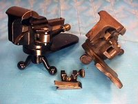
I threw in a pic of a vice clamp I have as a reference of the swivel handle that Joe Michaels mentioned for anyone else finding this thread. The other pic is a quick and crude idea of what Joe suggested as a way to reverse engineer this. You're also then suggesting I use a double-threaded stud like this one along with the clamping handles found at Item No: TM-3A [Tapped Two-Arm Offset Clamping Handle] and Item No: TM-3B [Tapped Two-Arm Offset Clamping Handle]?

The only thing I don't see is a way to permanently secure the malleable ball handle to the threaded stud. Sticking a locking nut on there would work but I'd hate it if the nut was loosened too easily from tightening and loosening the clamping bolt very often. A quick weld or maybe even a lock washer might be good enough though. In any case, I'm sure I can make something work.

GEDC0146.jpg GEDC0149.jpg

Thanks!
Jeff
 
epoclaen,

Your vise is the 'common or garden' variety of 'combination bench and pipe vise', as made by the Yost and Reed companies well into the mid-1930's, according to old catalogue listings.

The swivel system, using the notched cast base bolted to the bench, with the body of the vise held down by a large nut on a stud which passed down through the bench, was a continuation of an earlier pattern used on machinists' type vises in the 1880's, and maybe earlier. That design had the advantage of simplicity and cheapness, and, as Joe mentioned, would allow for the body of the vise to be mounted easily to an improvised or temporary job-site bench.

The original under-bench nut, for the Reed make (and your Yost vise is a copy of the Reed pattern, so the nut was probably the same as well), was a fairly heavy cast iron part, with the suitable tapped hole in the centre, and ends brought out into a 'ram's horn' configuration. It would have been approx 8" across the 'horns'. It was, for all practical purpose, a heavy wing-nut which could be tightened quite firmly with a moderately long bar through the 'horns'.

Any good blacksmith could make a 'period' looking forged nut, from, say, a short length of 1-1/4x4 flat mild steel, drawing out the ends to a gracefully tapered round, and curling them up nicely to resemble 'horns'.

Back in the 'real world', a suitable thick washer and heavy-hex pattern nut will put your vise in service quite adequately......... : )

cheers

Carla
 
epoclaen,


Any good blacksmith could make a 'period' looking forged nut, from, say, a short length of 1-1/4x4 flat mild steel, drawing out the ends to a gracefully tapered round, and curling them up nicely to resemble 'horns'.

Back in the 'real world', a suitable thick washer and heavy-hex pattern nut will put your vise in service quite adequately......... : )

cheers

Carla

And here's a nice description of a blacksmith making wing nuts from the iForgeiron site. Note that he has 3 "blueprints" for wing nuts--this link is just to the first.

BP1036 Wing Nuts 01 - Uri Hofi Series - Articles - Articles - I Forge Iron


Back
Top