What's new
What's new

2J1-1/2 head refurbish progress, plus some questions

Randalthor

Cast Iron
Joined
Mar 7, 2018
Location
Kansas City
There's probably a bazillion threads on head refurbishment, but perhaps I can add a little help to new BP hobbyists who are planning to tear into the head. My input is in no way definitive, I'm as new to this as anyone. I also have some questions at the end for any of the experts here please. The first part is just for anyone new, like me, so everyone else can scroll down to the questions if you want.

I bought this Bridgeport mill a couple of weeks ago and posted about the purchase and my basic tear down of the mill here.

http://www.practicalmachinist.com/v...hes/another-bridgeport-price-question-347638/

I'm a little further along now (have other obligations so can't work on it as much as I'd like). I currently have all the bearings replaced in the gear assembly and have the gear assembly back together.

KIMG0698[1].jpg

Disassembly generally wasn't hard. You obviously need to have a little mechanical knowledge (little things like orienting snap rings the correct way are assumed knowledge). You need to have equip. to press bearings out, and things to match the races of the bearings. Various pieces of pvc pipe or a 3/4" socket set works most of the time. I watched all the H&W machine videos, plus another set of videos put out by the Machinery Repair Shop, and read the book, "Guide to Renovating the Bridgeport 2J". If you are doing the work for the first time, get the book, it's worth the $25. I also recommend lots of plastic sandwich bags to put parts in, and a marker to label bags. Also a good idea to take lots of pictures during disassembly. This may not help if the head has been apart before, as there is no guarantee of the competency of the previous work.

One thing the book recommends is buying a 2" i.d. automotive lock nut socket to take off the slotted lock nut on the bull gear assembly, and not to use a punch and hammer to remove the nut (like I've done many times). I decided to follow the book's advice and bought the socket for $15. The socket didn't fit perfectly, so I had to touch up the dogs on a grinder to make it fit the nut. The socket was extremely helpful. It took a lot of force with a 2' breaker bar to loosen the nut. Even with the socket, it deformed the slots in the nut some. I can't imagine how that nut would have looked had I tried to remove it with a hammer and punch.

KIMG0700[1].jpg

In reassembling the bull gear assembly, I was a little unclear where to put the wavy washer. If you look very carefully in slow motion on this H&W video, the wavy washer comes out at exactly 1:38 It comes out right after the bearing in the end opposite the flange, of the bearing housing.

Disassembly of the Large Bull Gear Housing - YouTube

Likewise, in this video by Machinery Repair Shop the wavy washer comes out at the same location on the end opposite the flange. (17:31).

Bridgeport Mill Variable speed drive (2J) disassembly part 3 - Back Gear disassembly - YouTube

Those two examples are exactly how mine came apart as well.

However, regarding the washer, the book says, "On the bottom of the sleeve (the flanged end) first install the WAVE SPRING WASHER on top of the snap ring, and then press a new 6908 double sealed ball bearing into the sleeve pressing only on the outer race." (emphasis in the original)

They even show pictures reinforcing their instructions to put the washer on the flange end, instead of the other end, like mine came apart.
KIMG0701[1].jpg

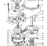
This caused me some consternation and fretting, especially since the book was emphatic on the point. Do I put it back together like it came apart, or follow the instructions of the book? I looked carefully at the Bridgeport schematic, and contrary to the book (and like the videos) it shows the washer belongs in the end opposite the flanged end (#58 in the drawing below). I decided to go with the way Bridgeport installed it and put it on the non-flanged end.

Screenshot-2018-3-24 M -0009500-0450 - SeiresIPartList pdf.jpg

Maybe it's not that big a deal, the Machinery Repair Shop rebuilder doesn't even put the wavy washer back in at all. (See vid starting at 1:07 and again at 6:00)

Bridgeport Mill Variable speed drive (2J) reassembly part 2 - Back Gear assembly - YouTube


On another issue, I've not been unable to find are any torque values for the fasteners on the head (except where the head mounts to the base). The actual Bridgeport service manual probably has that information, but I don't have that book. I've just been torquing them by feel according to the size of the fastener. I also use a bit of blue loctite with the fasteners, which may be controversial, but I don't like fasteners coming loose by themselves. Even the slotted nut on the bull gear assembly I mentioned earlier seems to have come loose in this vid. (see 0.32 min)

Disassembly of the Large Bull Gear Housing - YouTube

Now for the questions.

The book says to fill the lower gear assembly with grease till it comes halfway up on the bull gear teeth, when the bull gear is in the upper position (high gear) and pack it in the pinion gear. I did that, but when I lowered the bull gear to engage the pinion gear, the grease really pushed up and over the top of the bull gear. The book says not to get grease on top of the bull gear, so I ended up taking a little bit of the grease back out. How do you know if you have the right amount of grease in there?

Secondly, and probably more importantly, I have a question on removing the spindle. I have the head tore down enough, that I could take the spindle out in 10 min. I've already had the nose cap off the quill to replace the collet alignment screw (it wasn't broken off, but badly worn). It would not take much more to tap the spindle out. I'd like to remove the spindle to examine the bearings, but I read on the PM forum once that you should not remove the spindle unless you absolutely have to. I've also read that a properly aligned spindle has to have the taper reground "in situ" with the quill.

I don't think this spindle has ever been out of this machine, so I don't want to screw up the alignment. I couldn't read any spindle runout on a magnetic indicator, so I think it's aligned fairly well. The reason I'd like to take it out to examine the bearings is that the timing pulley clutch sleeve (see #38 in the schematic drawing above) had come off at some point and ground a little bit off by hitting the bull gear below(the sleeve didn't touch the dogs on the bull gear hub (#39), the dogs are in very good shape on the upper and lower shaft and have a very tight fit).

KIMG0702[1].jpg

I bought a new sleeve and plan to use bearing retaining compound to keep it on the upper shaft, but the problem is when the old sleeve ran against the bull gear it scraped some shavings off and I found these in the felt washer below. Moreover, some of the metal shavings made it past the felt washer and I found them in the quill nose cap, which I had removed to take out the worn collet alignment screw. I'm concerned there could still be some metal shavings on top of the lower spindle bearing, and would like to remove the spindle to examine (as I mentioned I have just about everything apart anyway). I just don't want to do it if it could throw the spindle out of alignment. Can someone who has experience in this please tell me the likelihood the spindle will come out of alignment with the quill by removing it? It's probably been discussed here many times already, but I searched for quite a while and couldn't find a thread which discussed it.
 
Last edited:
Just a couple of comments on some of what's mentioned above:

1. I also mostly used PVC pipe segments and sockets to drive my bearings in. A few drifts I had to custom machine on my lathe though (like the one used for installing the motor bearing).

2. I had the exact same question you did on the wavy washer and went through the exact same process of hyper-scrutinizing those two videos showing exactly where it popped out. Mine came apart the same way and that's also how I reinstalled the new one.

3. I used the punch method to remove and reinstall the slotted lock nut on the bull gear assembly. Had no issues getting the nut either on or off this way. I feel it is an acceptable method as long as it's done judiciously.

4. I just torqued everything by feel during reassembly. I've been working on machines for a long time and have pretty good judgement on how much torque is reasonable depending on bolt/nut size and application. (although I do use a torque wrench for critical fasteners like cylinder head bolts etc)

5. I didn't use loctite as I didn't see that it was used during original assembly.

6. I just filled the grease cavity about how you have yours there and moved the bull gear up and down so that it squished some of it upwards. Made sure it could be moved up and down without resistance. I also put some into the cavity surrounding the bull pinion gear, even though the bearings are sealed.

7. I did not remove my spindle. Mine was tight and I did not want to disturb the alignment gods. What I did is thoroughly clean the area above the felt washer with paper towels, solvent and a shop vac with a small (~3/4" dia) hose attachment to get down into the crevasses of the area. I also used a powerful magnetic probe to help pick up any loose chips or metal filings. Once I was sure the area was surgically clean, only then did I remove the felt washer. I then inspected the exposed upper bearing, which appeared fine. Once again I used a clean magnetic probe to attempt to pick up any metal filings or debris in the open bearing area. Nothing came out, so I vacuumed the bearing thoroughly with the small hose attachment followed by flushing the upper and lower bearing with some fresh spindle oil while rotating by hand. I don't think this really did anything, but I wanted to help get any gunk out of there that may have fallen into the bearing area over the past 50 years. I then carefully reinstalled the new felt washer, seated it properly and pre-lubricated everything with more spindle oil.
 
Maschine,

So far it sounds like I've done everything almost the same as you did, except with the loctite (I also didn't vacuum the top spindle bearing or use a mechanical probe, but did clean that cavity as best I could. I removed the worm gear cradle for the spindle down feed, which is in that cavity, so that allowed me pretty good access.)

I'm glad I have someone to copy during this process who thinks a lot like me on mechanics. Your advice has been extremely helpful. Little things like replacing the felt washer, good ideas.

I agree with you on the loctite, the original factory assembly doesn't use it. Maybe I'm OCD about fasteners coming loose. I use loctite on all my equipment. I hate it when I see a fastener missing.

One other thing which has caused me some pondering is the housing for the top spindle pulley bearing (#22), which attaches to the speed change plate (#13). (Btw, apologize for the small appearance. I don't know how to upload a proper screenshot on this forum.) I have the bearing for it, but haven't replaced it yet.

Screenshot-2018-3-24 M -0009500-0450 - SeiresIPartList pdf(1).jpg

The housing, from external appearance, does not look like it runs true. Notice the housing is closer to one side of the shaft vs. the other.

KIMG0705[1].jpg

I thought maybe the housing was bent at some point. But I've measured very carefully from the screw holes and the distance from the holes to the outside of the pulley remain constant as the housing is turned on the shaft. Additionally, the distance from the housing to the pulley, vertical wise (where it's mounted in the pic) remains constant as it's turned. Lastly, there was no evidence the housing is "wobbling" on the speed change plate. I looked that over carefully and it would show evidence of wobbling if the housing was bent because the screws and spacers which fasten the housing to the speed change plate are a loose fit from the factory.

I finally came to the conclusion the housing was just casted that way, but when the screw holes and bore were machined in the housing, they were machined to center everything correctly, that is, everything that counts.
 
I can see what you're saying about the out of alignment thing. Unfortunately, my machine is already back together and I don't recall seeing what you have there. Although maybe it was like that and I just didn't notice it? Dunno. But really, as long as you know nothing is bent or improperly assembled it could be just how the casting is. The aluminum bearing sliding housing (or whatever they call it) doesn't rotate, it only applies pressure to the bearing from the lever connected to the 2 (or 1?) allen bolts. So a slight offset probably wont matter anyway...maybe. ;-)

As far as loctite, I'm not sure how long loctite has been in common use (I know it's been around since the 50's or 60's). But I believe it didn't really come into vogue until the 70's. So it may be that the only reason they didn't use it on my '69 was because it wasn't really common practice back then. Wouldn't hurt to use the lighter grade stuff during reassembly IMO, and is probably a good idea.


image.img
 
The only alignment is the spur gear to the rack on the quill and that falls naturally into place. Forget about the "mystery alignment".
If the quill is to be removed remove the two screws at the top of the quill. They hold the dust shield in place. Remember the
position of each screw as one is a bit shorter for clearance. Be sure to replace the spindle bearings in the same orientation as they are removed.

The thrust face is not always marked. It is the thicker outer face of the bearing.

Bridgeport used to build the head with a zerk fitting at the back of the housing #54 and level with the pinion gear. Grease was to be applied thru
this zerk while the mill ran in low range-low rpm. As the mill runs grease with fines and other wear particles is spattered on the inside wall of the cavity. A regular maintenance interval would refresh the grease for the bull gear and the pinion and the gear teeth would stay cleaner.

Packing the cavity with grease gives no place for the contaminated grease to go. There is no way to churn or refresh the grease.

The two bearings in the housing #22 rarely go bad but they will tend to run dry. Use a dental pick to pop the seal on one side to regrease.
That grease you put in the bull gear cavity looks like light electric motor grease for bearings and should suffice.

Bearing #4 in the upper housing #2 is prone to failure as it must withstand the side load from the drive belt. If it does fail it will lock up and
score the journal diameter.

John
 
The aluminum bearing sliding housing (or whatever they call it) doesn't rotate, it only applies pressure to the bearing from the lever connected to the 2 (or 1?) allen bolts. So a slight offset probably wont matter anyway...maybe. ;-)

I probably wasn't very clear in my previous post, or maybe I mistook your comment. Although I knew #22 didn't rotate, I thought if it was somehow out of alignment with the bearing inside (and shaft #33 the bearing goes into) it would wobble and show some wear marks on bracket #13, where bushings #19 go through the holes (my bracket has two holes). Do you think that's sound reasoning?

John,

Thanks for the response. I haven't ever had the spindle out, so it's a little hard for me to follow.

Re: "Be sure to replace the spindle bearings in the same orientation as they are removed.

The thrust face is not always marked. It is the thicker outer face of the bearing."

Would that matter if I don't remove the spindle bearings (I don't plan to) just the spindle, with bearings attached? In that case, would I need to worry about index marking the bearings (with a marker)to get them back in the quill at the same spot (Quite frankly I don't think I could get them both in the same exact spot, even if I marked them.)

The book I have says the proper way to replace spindle bearings (even though I don't have plans for replacing them) is to send the spindle and quill to a professional service to have them install the spindle bearings and then they regrind the spindle taper in situ while it's in the quill. That sort of implies to me the spindle is perfectly mated to the quill and should not be removed? Am I overthinking this?

Btw, the grease is the Mobilux EP1 grease H&W sent with the rebuild kit. I don't know if that's the same grease used in electric motors or not.

My head has the exact same hole you mention (called the "B" port on my lube plate). It doesn't have a grease zerk, but what you say makes perfect sense.
 
I knew #22 didn't rotate, I thought if it was somehow out of alignment with the bearing inside

What you see is typical for this part #22, rest assured that is correctly manufactured. Concern can be directed at the two sleeves #19.
They should be in good shape and if not order three replacements. The third is for the visually impaired for when one hides out on the floor.
Not something that is usually replaced as they may last the life of the machine but deserves a look.


I haven't ever had the spindle out.

The quill is the complete assembly, hard chrome plated and has the milled rack on the back side.
The spindle is the splined shaft-bearing assembly. The splined shaft accepts the drawbar at one end and has the R-8 taper at the other.

Re: "Be sure to replace the spindle bearings in the same orientation as they are removed.

The thrust face is not always marked. It is the thicker outer face of the bearing."

Would that matter if I don't remove the spindle bearings (I don't plan to) just the spindle, with bearings attached? In that case, would I need to worry about index marking the bearings (with a marker)to get them back in the quill at the same spot (Quite frankly I don't think I could get them both in the same exact spot, even if I marked them.)

If the bearings are left in situ and undisturbed there is no worry. All three bearings are precision grade, ABEC 7 for the lower set. They should be a duplex set of thrust bearings and are ground on one face of each bearing so that they will seat in the race and prevent axial movement while still allowing a minimal space for oil in the groove. The amount ground off the two faces amounts to the preload the set has. This preload depends on the the two spacers between the bearings being the same length with parallel faces.

The thrust bearings are typically marked with a high spot that identifies maximum axial runout on the inner and outer races. Alignment is to orientate the inner marks together and also to orientate the outer race high spot marks at the time of assembly.
The bearing at the top of the set should also be a precision bearing to avoid axial oscillation
.

Quill removal is necessary when the downward pressure to extend the quill is excessive. I would consider removing the quill to clean the O.D. and the bore if there is a loss of "touch or feel" when drilling and tapping small holes like for a 5-40 tap.
Difficulty may be found with the quill skirt (dust shield) removal and replacement.


The book I have says the proper way to replace spindle bearings (even though I don't have plans for replacing them) is to send the spindle and quill to a professional service to have them install the spindle bearings and then they regrind the spindle taper in situ while it's in the quill. That sort of implies to me the spindle is perfectly mated to the quill and should not be removed? Am I overthinking this?

Orientation of the pairs of high spots is accurate enough.
Sorry, don't have the book and if I did might peruse it once to see if it was accurate and then put it on the shelf. I do not watch U-tube how-to's either.
Likely you will never make watch parts or anything so small that this kind of service is needed. The missing step is to install an accurate R-8 collet and a small test bar of a concentricity that is known to be accurate and check for run-out!


The grinding operation removes any eccentric motion vis-a-vis the bearings and the taper. Very useful if the taper has been distorted/damaged by dirt and chips. There are also services that will regrind the R-8 taper and they come to you. The quill remains in the head. Of course this is somewhat useless if the R-8 collets and tool holders are clapped out.


Btw, the grease is the Mobilux EP1 grease H&W sent with the rebuild kit. I don't know if that's the same grease used in electric motors or not.

The EP grease should be fine but IMHO there is way too much of it in that cavity. I like the red Mobile synthetic as it will dissolve in oil.

My head has the exact same hole you mention (called the "B" port on my lube plate). It doesn't have a grease zerk, but what you say makes perfect sense.

Sounds like you have a pretty good handle on what's going on here.
John
 
Thanks John,

I checked the two sleeves (#22) and they don't seem to have much wear. The difference in O.D. is .003 from the most worn part to the unworn part of the sleeve. The sleeve itself has a wall thickness of .040, so that didn't seem like much wear to me.

Re: Spindle removal

That was a really great explanation. I wasn't planning on removing the quill because it feeds up and down nice and smooth.

I can see what you are saying about the spindle taper ground to match the bearings. That makes sense that would get the runout to near zero. After I thought about it a bit, grinding the taper while it's in the quill wouldn't reduce runout at all, because the bearings, in relation to the spindle, determine the runout, the quill wouldn't have anything to do with it. Even if the spindle was cock-eyed in the quill, it still wouldn't affect runout, although the tools wouldn't be in a straight plane with the quill. The quill could only affect runout if there was a lot of slop between the outer races of the bearings and the i.d. of the quill. I'm sure you already well know all this, but I'm just now starting to figure it out. If I have it right, it feels a bit liberating. I think I will pull the spindle out to examine it, although I won't touch the spindle bearing pack.

I looked at the book again, and they just say sending the quill in with the spindle to have the taper reground will limit runout to an absolute minimum, but again I don't see how having the spindle in it's own quill while regrinding would lessen runout.

Here's the reference of it in the book, if you are interested.

KIMG0715[1].jpg

I seemed to have solved another mystery (for me) today. The lower timing belt had been dragging on the aluminum shield (#56) and I didn't know why. I thought maybe the large timing belt pulley was out of alignment, or perhaps the bull gear pinion was out of alignment. However, the spindle pulley shaft (#33) was missing the clutch sleeve (not shown in the schematic above). It had fallen off and was sitting on top of the aluminum plate, when I took things apart. I didn't know what that sleeve was for until I pressed it back on the shaft, at the end with the dogs. Then I realized the purpose of that little sleeve. It keeps the timing belt in alignment. Although probably old news for you, it was another ah,ha moment for me. Here's a pic of what I'm trying to reference. Notice the gouged aluminum plate in the background. I put the new sleeve on with bearing retaining compound this time, although it was a pretty hard press to put it on anyway.

KIMG0710[1].jpg

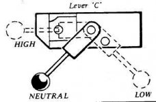
I did have another question regarding adjusting the Hi/Lo detent plate. Mine has the little allen screw for adjustment, but the book says to adjust it so the bull gear perfectly lines up with the pinion. But I've read people adjust it a little to match the dogs of shaft #33 and it's mate (not shown above). How do I do that? There is no way to see if they are mated perfectly with everything together.
 
The adjustable plate has two semi-circular knock-outs for the neutral detent position so after excessive wear the
plate can be removed, rotated 180 degrees, and then replaced back into the slot. The plate is held on location by
a very small set screw. Moving the plate up or down will alter the engagement of the upper and lower radial drive splines on the two hubs and also affect the neutral point. Wear will change the shape of the splines from a square to a trapezoid. A lot like an acme thread profile rather than a square thread. The square thread profile is much like the crown gear on the handle for the knee. This sloped shape causes the hubs to push away under load, especially during intermittent contact when milling with something like a three insert carbide mill. The gap that results will cause a lot of clatter during the cut.

If the machine has the adjustable plate for the Hi-Lo here is what to do.
Loosen the set screw just enough so that the plate will slide up or down with the detent fully engaged.
Engage Hi-range and start the mill and set the rpm to 500-600.
You will move the detent in small increments.It is important to listen to the sound of the head prior to changing the position. Upwards engages the splines/hubs together. As the engagement reaches a point of overtravel the sound from the head will change from smooth to a strain or louder deeper hum sound. Move the Handle ccw until this sound diminishes. Try this a couple of times and screw in the set screw when it has a light or no strain sound.
Now engage the handle at the neutral detent. Be Sure that neutral engages cleanly and without contact, rotate the spindle. If not readjust the detent position for Hi ccw until a happy medium for both detent positions of Hi and Neutral is achieved.

Overtravel in the cw direction will also bring the bull gear up until it contacts the grease cover. This is a different sound so listen for it. Something like a soft scrape interference noise. I think I remember that the cover can be reversed, installed upside down, and if this is the case there will be an interference.

This adjustment does not in any way affect the location of the Lo speed detent.

This is the old style Hi-Lo plate. I used to make these because they are no longer available. The Hi-Lo plate sold today has only one setting and there is no adjustment for wear to the splines on the hubs. If you have the old type consider yourself lucky. The alternate fix for reducing hub noise is to purchase new upper and lower hubs. Bean Counters.....at work.
Backgear Assembly.JPGHi-Lo Lever.JPGHi-Lo Adjustable Plate.jpg


Some other parts images ;
~Top Housing Parts.jpgLower Housing Parts.jpg
John
 
Re: Spindle removal

That was a really great explanation. I wasn't planning on removing the quill because it feeds up and down nice and smooth.

I can see what you are saying about the spindle taper ground to match the bearings. That makes sense that would get the runout to near zero. After I thought about it a bit, grinding the taper while it's in the quill wouldn't reduce runout at all, because the bearings, in relation to the spindle, determine the runout, the quill wouldn't have anything to do with it. Even if the spindle was cock-eyed in the quill, it still wouldn't affect runout, although the tools wouldn't be in a straight plane with the quill. The quill could only affect runout if there was a lot of slop between the outer races of the bearings and the i.d. of the quill. I'm sure you already well know all this, but I'm just now starting to figure it out. If I have it right, it feels a bit liberating. I think I will pull the spindle out to examine it, although I won't touch the spindle bearing pack.

I looked at the book again, and they just say sending the quill in with the spindle to have the taper reground will limit runout to an absolute minimum, but again I don't see how having the spindle in it's own quill while regrinding would lessen runout.

Yes, ground while as an assembly in the quill is the preferred way to do this.
However, unless one is ready to spend large dollars on a precision set of collets and toolholders ....................................

.

Once assembled the spindle cannot be out of alignment w/r/t the quill unless the bearings are shot or the spacers do not have matched lengths. There is no need to take it apart unless it is for a future benefit of assembly knowledge. Make sure it is oiled and that the top felt is clean and in place. Remember that the head rotates and swings up and back(nods as some say) and these features help set the head to the table, vise, or part surface.

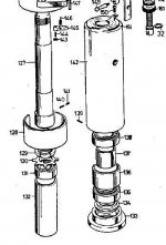
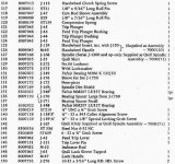
Some spindle views:
Spindle Assembly.JPGSpindle explode.jpgQuill-Spindle Parts List.jpgSpindle Bottom.jpg
John
 
John, thanks for another swell explanation. I didn't take the hi/lo shift plate apart (and didn't really look iat it very closely) so I didn't understand how the detent adjustment worked. I see now how the center hole (for the high speed detent) is off-set from the edges (so the hole is really not centered) to allow it to be flipped over for extra adjustment. Nifty design. Too bad Bridgeport did away with it, for a cheaper, easy one piece detent plate.

I'll plan on adjusting it like you advised. Thank you.

You mentioned earlier I had too much grease in the bull gear housing. I haven't put the sections together yet, so I can easily take off the aluminum cover plate and remove some grease. How can I tell how much grease should be in there? In the picture of my original post above, it's in the low gear setting and the pinion cavity is packed full of grease. In the larger cavity, the grease is just coming up to top of the two meshed gears.
 

Basically what I am saying is that if the spindle R-8 is reground then precision collets would need to be purchased to recoup the benefit of grinding. Most new collets will have run out in the tenths. The type of work performed might justify a regrind but Bridgeports are not precision
jig borers.

Lacking a zerk fitting the grease ought to stay. Otherwise the amount needed should be a quantity that just coats the face of the gear teeth, reapplied at maintenance intervals dependent on use. The missing zerk fitting might have been a Textron change.
 
Last edited:
That quote is from your post #8 about the third paragraph down.
Basically what I am saying is that if the spindle R-8 is reground then precision collets would need to be purchased to recoup the benefit of grinding. Most new collets will have run out in the tenths. The type of work performed might justify a regrind but Bridgeports are not precision
jig borers.

Oh OK, sorry. I thought the italicized text was from someone else. I didn't realize you were responding to me in both the blue box and the text below.

I'll edit post #12 as an error on my part.

The head on my machine has the threaded port in the back. Would you advise installing a grease zerk (assuming the threads match) and using it?

I've been thinking a little more about removing the spindle. After further thought, I don't think I will. I've seen the insides of gear boxes before, and all the gears/bearings look shiny from oil. Unless there is a problem, there's no reason to open them up. The top bearing under the felt washer looked shiny, as one would expect. If anything washed through that bearing, I'm sure it's small enough to wash through the other two. The small metal fines I saw behind the quill nose cap might have come from parts being machined below?
 
That is what I would do if the threaded hole is thru to the housing and those are tapered pipe threads. Install a zerk fitting.
Scoop out the excess grease(most of it) and save it to apply at monthly intervals or longer. As the mill runs in high speed the grease will be thrown off, self cleaning. The Bridgeports I have worked on that have the cavity filled with grease end up with an air pocket around the gears. The blob of grease just sits in there. I would remove the dirty layer revealing the rest of the grease to be as clean as the day it was put in.

Maintenance greasing entails two or three pumps of grease while the mill is in Lo range rpm. If it needs grease there will be a change in pitch (sound) as the grease coats the face of the gears. Initially when the pinion gear cavity is empty of grease (the small spur gear of the set) the excess grease will fill this first. Over time it should take slightly less grease applied to get to the bull gear.
John
 
Last edited:
Wanted to update. I cleaned out all the (fresh) grease out of the lower gear housing. It made sense about the cavity being there as a "waste" area to accept spent grease. Indeed, when I pulled this head apart, I noticed the bull gear was dry and all the grease was plastered against the sides. Interestingly, the bull gear and pinion looked like they didn't show any wear at all, even though they probably hadn't had grease b/t their teeth for a while.

It made sense about feeding grease in back of the pinion bearing at that opening to splay grease on the bull and pinion gear. And since that was a Bridgeport original design for this machine, I wanted revert to that. It has a threaded hole at the back of the lower gear housing. Someone put a threaded allen screw in that hole, but I am working on putting a grease zerk there. I don't know how often grease is required there. Anyone know how many hours b/t greasing? Perhaps I will make up a sticker to paste on for instructions. A good sticker is only about 5 bucks on ebay.

KIMG0716[1].jpg

I suspect Bridgeport changed the design later because a grease zerk at the back was a big liability. I'm a farmer, and I know from experience, when there is a grease zerk, there is a tendency of one of two extremes. Some folks completely ignore maintenance and never touch a zerk till the machine fails, others grease it every time they see it. I suspect Brigeport came up with a "happy" medium to pack the lower gear cavity with grease, avoiding the negligent person, and the overzealous both.

There is a "B" hole on the back of the lower housing on this machine. This is the hole which would require grease for the bull gear and it's pinion. I've stuck a small screw driver in this hole and able to turn the pinion gear.

I'm going to put a zerk in this hole to be able to grease it accordingly. I haven't yet been able to determine the size of the hole, but I pulled out an allen screw of fine thread which was a perfect fit.

I had to make something to compress the spring on the vari speed motor pulley. It doesn't take much. I just used a long 1/2 bolt with some washers to compress the spring.

KIMG0719[1].jpg

Finally I put the new bushings in the pulleys with the glue.

KIMG0720[1].jpg
 
This adjustment does not in any way affect the location of the Lo speed detent.

This is the old style Hi-Lo plate. I used to make these because they are no longer available. The Hi-Lo plate sold today has only one setting and there is no adjustment for wear to the splines on the hubs. If you have the old type consider yourself lucky. The alternate fix for reducing hub noise is to purchase new upper and lower hubs. Bean Counters.....at work.
View attachment 224113View attachment 224114View attachment 224115


Some other parts images ;
View attachment 224120View attachment 224121
John

John,

My hi/lo lever doesn't look like the one pictured in the images above. It does have the adjustable detent plate, but the handle doesn't have the two adjustable allen screws to adjust the bull gear alignment with the pinion. Instead it's got a roll pin holding the handle on. Have you ever seen that type? If so, is it adjustable for bull gear alignment w/ pinion?

My bull gear is just slightly out of alignment and I'd like to get a perfect match of the teeth.

Here's a pic.

KIMG0723[1].jpg
 
Easier to do than describe but here is a shot at it. There are a few variables so go to the one constant that remains the same.
Lo-range is set by the detent plate and the timing of shaft splines to the milled rack of teeth on the bearing sleeve. The bearing sleeve is what raises and lowers the bull gear assembly for Hi & Lo range.
The timing of the shaft to the sleeve can be checked by withdrawing the shaft, then reinsert it one spline advanced or one behind. Then recheck gear face engagement. Originally this was set for gear face engagement and the hole for the roll pin was positioned to hold this Lo-range detent location. The variable here is the location of the roll pin hole, if changing the timing of the spline shaft to the bearing sleeve does not help the roll pin hole could be relocated. Usually one ends up going back to the original spline location as it gets to be a sticky amount of work for a minor change.
Consider that if the gears have been engaged with the faces offset it might be better to leave it so as there will be a wear pattern.
Adjustable allen screws? Long time since I've seen those but thought they were for clamping the handle to the end of the shaft.
John
 
Consider that if the gears have been engaged with the faces offset it might be better to leave it so as there will be a wear pattern.
Adjustable allen screws? Long time since I've seen those but thought they were for clamping the handle to the end of the shaft.
John

Thanks John,

I'll probably just leave it where it's at. The bull gear and pinion are very close. I had wondered if the roll pin held the handle by way of a trough cut into the shaft which the handle goes on, with some sort of splines. In other words I had wondered if the handle had splines (I'm not referring to the splines on the big end of the shaft, but the part which holds the handle, the little end (#11 in the third schematic in your post 17). If that part was splined, then the little shaft it pushes onto (#59) would be splined on that end, and one could pull the handle off and move it to perfectly line the bull gear and pinion when the handle is in the low speed detent.

It sounds like your saying the roll pin goes through the middle of the handle and so the position of the handle on the shaft can't be moved, unless I wanted to drill another hole.

On the type of handle you show above, it has the two allen screws, and the book shows to loosen those and move the handle to align the bull gear with the pinion so that when the handle is in the low speed detent, the gears are perfectly aligned.

KIMG0732[1].jpg

BTW, just in case someone wants to set up the Bridgeport with the grease zerk at the back of the head, the hole in mine was a 5/16 fine thread. It wasn't a pipe thread, which is what I expected. 5/16-24 bolt fits it perfectly. I couldn't find that sized zerk at the local auto stores, so I had to end up getting it off Ebay.
 
It sounds like your saying the roll pin goes through the middle of the handle and so the position of the handle on the shaft can't be moved, unless I wanted to drill another hole.
.
Right, that's it. The old type handle style was given a KISS. The old style would slip over time and require adjustment. Manufacturing time was higher.


Back
Top